2013 GT500 pump wiring

rojizostang

i love my cams
S197 Team Member
Joined
Apr 26, 2008
Posts
5,505
Reaction score
19
Location
san antonio, texas
I posted a link to ebay where I purchased the upgraded gt500 intercooler pump. I decided to start a new thread, thinking not everyone is looking at it.

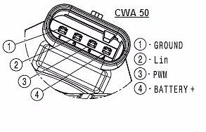
On the ebay listing, the instructions for the newer pumps say to jumper pins 3 and 4 and apply 12v there, and then ground pin1 for the pump to run at full speed.

the harness I bought only utilizes pins 1 and 4.

Can anyone confirm that the pumps indeed run at full speed only when jumpering out 3 and 4 and grounding 1?

here are the links to ebay where the instructions for the pump is

http://www.ebay.com/itm/301868988494?_trksid=p2060353.m1438.l2649&ssPageName=STRK:MEBIDX:IT

this is the jumper I bought, it appears this won't run the pump at full capacity
http://www.ebay.com/itm/222070744960?_trksid=p2055119.m1438.l2649&ssPageName=STRK:MEBIDX:IT
this harness should allow the jumper instead and run the pump at full speed:
http://www.tascaparts.com/oe-ford/cu2z14s411aya

for anyone reading this post, I edited it several times before getting all the information in here. Basically, anyone using the newer pump, if they're only using pins 1 and 4, they probably aren't utilizing the pump at full speed.

can anyone confirm the proper wiring to run the pump at full speed?
 

Attachments

  • pumpwiring.jpg
    pumpwiring.jpg
    14.8 KB · Views: 83
Last edited:

Wes06

forum member
Joined
Jan 21, 2012
Posts
5,383
Reaction score
59
hmm, interesting

seems like a question for Sqidd!
 

rojizostang

i love my cams
S197 Team Member
Joined
Apr 26, 2008
Posts
5,505
Reaction score
19
Location
san antonio, texas
The pump runs off of pins 1 and 4.

2 and 3 are not used.

i understand in a standard ford gt500 application, those pins aren't used. this pump however is used for several different applications, other than ford.

point being, if the ebay instructions are correct, we are leaving some of the pump's capacity laying on the table.

and not to belabor the point, I was respectfully wondering in all the testing that you've done, if you explored to variable speed capability of this pump? I don't remember reading about that in your thread(s), but I didn't read every single post or paragraph.

if you did, that's awesome and i won't have to waste my time trying to determine what the pump's capabilities are, thanks man!
 

Department Of Boost

Alpha Geek
Joined
May 26, 2010
Posts
8,809
Reaction score
28
i understand in a standard ford gt500 application, those pins aren't used. this pump however is used for several different applications, other than ford.

point being, if the ebay instructions are correct, we are leaving some of the pump's capacity laying on the table.

and not to belabor the point, I was respectfully wondering in all the testing that you've done, if you explored to variable speed capability of this pump? I don't remember reading about that in your thread(s), but I didn't read every single post or paragraph.

if you did, that's awesome and i won't have to waste my time trying to determine what the pump's capabilities are, thanks man!

I have not explored the variable speed capabilities. I just ran them wide open using pin 1 and 4.

I don't see why someone would ever want it running less than WOT. At least not in our applications.

Now, if the CWA50 that you got off eBay is somehow "programmed" different than the OEM GT500 pump and pins 2 and 3 need to be screwed with IDK. I suppose that's a possibility. I've had the CWA50 and the GT500 version in my hand and they are identical. And I'm not sure what could be different internally that would cause them to run differently assuming they have the same inputs. Just a guess of course.
 

rojizostang

i love my cams
S197 Team Member
Joined
Apr 26, 2008
Posts
5,505
Reaction score
19
Location
san antonio, texas
well in the ad, it mentions tying pins 3 and 4 together, instead of the middle two pins, and the other is ground, number 1.

my guess here would be that tying 3 and 4 together utilizes another set of windings within the motor itself that would result in an increased pump speed. It would work sort of like a tap changer on a power transformer. changing taps effects the desired output voltage.

adding another set of windings within the motor itself by tying 3 and 4 together, in my mind's eye at least, would have the same effect, as your are adding more copper wiring on the armature resulting in a higher electrical current capacity of the pump, resulting in it's ability for more speed? might be off a little bit in my reasoning, but I think that it's a likelihood that the pump can run at a greater volume than which you tested.

also mentioned in the ad is that there is an external controller being made available by the same supplier of the pump, which my guess is nothing more than a switching device, rather than a rheostat which would externally control pump voltage, which of course could effect pump speed.
 
Last edited:

Department Of Boost

Alpha Geek
Joined
May 26, 2010
Posts
8,809
Reaction score
28
well in the ad, it mentions tying pins 3 and 4 together, instead of the middle two pins, and the other is ground, number 1.

my guess here would be that tying 3 and 4 together utilizes another set of windings within the motor itself that would result in an increased pump speed. It would work sort of like a tap changer on a power transformer. changing taps effects the desired output voltage.

adding another set of windings within the motor itself by tying 3 and 4 together, in my mind's eye at least, would have the same effect, as your are adding more copper wiring on the armature resulting in a higher electrical current capacity of the pump, resulting in it's ability for more speed? might be off a little bit in my reasoning, but I think that it's a likelihood that the pump can run at a greater volume than which you tested.

also mentioned in the ad is that there is an external controller being made available by the same supplier of the pump, which my guess is nothing more than a switching device, rather than a rheostat which would externally control pump voltage, which of course could effect pump speed.

I would be shocked if that pump moved more water than what I tested. SHOCKED.

And if it were possible why didn't Ford take advantage of it?
 

rojizostang

i love my cams
S197 Team Member
Joined
Apr 26, 2008
Posts
5,505
Reaction score
19
Location
san antonio, texas
I think I will order the other jumper and play around with the pump before I install it to detect if there is any noticeable difference in speed.

I just don't want to burn up a brand new pump by applying voltage where it doesn't belong!

I would be shocked if that pump moved more water than what I tested. SHOCKED.

And if it were possible why didn't Ford take advantage of it?

well, not to rehash all the things that you and the other folks (engineers) hashed out in your thread, my suspicion would be that utilizing the pump at a certain speed would be of benefit within a specifically designed cooling system.

a higher speed on that pump may work better on another system, with a different arrangement of intercooler/heat exchanger.

it seemed the consensus of the thread by the guys who were pasting the graphs in were saying that improved flow up to a point is beneficial...not to argue with you at all or the findings and data that you came up with.

I do know this....when we were kids, we would remove the thermostats from our small block fords, and they would run hotter. we would install a washer style restrictor in the thermostat housing to slow the water down a little, and the motors would run cooler.
 
Last edited:

Department Of Boost

Alpha Geek
Joined
May 26, 2010
Posts
8,809
Reaction score
28
it seemed the consensus of the thread by the guys who were pasting the graphs in were saying that improved flow up to a point is beneficial..

I think that was roughly 20gpm? The GT500 pump isn't even close to that.

And that was based on a very rough model with let call it "light" parameters. I know, because I'm the one who provided them. Data collected from a model is only as good as the data that was used to build it.

Data collected in real life on the other hand is good. And I have tons of real world data on actual systems run in the real world. Probably more than anyone else. Probably more than most people combined. Universally more water flow has resulted in lower IAT's up to 26gpm which is as high as I have tested.

People can listen to me, or they can ignore me. I really don't give a fuck. I don't sell pumps.

It's not because of you, but I'm now bowing out of this thread just like I did the other one. I refuse to argue with calculator cowboys who ache to be right all the time and are using very rough data. They will be along shortly.
 

rojizostang

i love my cams
S197 Team Member
Joined
Apr 26, 2008
Posts
5,505
Reaction score
19
Location
san antonio, texas
My apologies. I had no intention of the thread spinning this direction.

The whole truth is solely my desire to find out about the ability of the pump in question, not to start a war with you or anyone else. I truly desired to find out if you knew that the pump could operate at different speeds, and if the described wiring in the ad is correct.

I'm still looking for that information, and would be more than happy for the thread to return to that point.
 

rojizostang

i love my cams
S197 Team Member
Joined
Apr 26, 2008
Posts
5,505
Reaction score
19
Location
san antonio, texas
FWIW, I have a call in to the manufacturer in order to find out specifically how the pump should be wired for full speed, and any other speeds that may be available.

I will post here if/when I hear back from them.
 

rojizostang

i love my cams
S197 Team Member
Joined
Apr 26, 2008
Posts
5,505
Reaction score
19
Location
san antonio, texas
Ok

I purchased a small set of jumpers so I can bench test this pump. It will only run with 3 and 4 jumpered out and 1 grounded. It will not run at all with power supplied to pins 1 and 4. So, I don't know what's going on with it.

On top of that, my pump is bad. It will start and run after a short delay of a few seconds, but then it rattles and stops.

Bummer. I think I'm going to return it and just forget about installing it. I'll just live with the ait's averaging about 120 degrees or so that it averages in normal driving. I'm not sure now that it's worth the headache of chasing this down and re-doing the whole cooling system.
 

eighty6gt

forum member
Joined
May 9, 2011
Posts
4,299
Reaction score
405
You put power to 4 and ground to 1 and it didn't run? Power supplied to 1 and 4 .. you mean power and ground, right?
 

rojizostang

i love my cams
S197 Team Member
Joined
Apr 26, 2008
Posts
5,505
Reaction score
19
Location
san antonio, texas
You put power to 4 and ground to 1 and it didn't run? Power supplied to 1 and 4 .. you mean power and ground, right?


yes

apparently this pump is wired differently. I broke out the volt ohm meter, and there's no continuity between 1 and 4....not without 3 and 4 being jumpered anyway.

i'm doing some research as we speak, trying to find out about this pump. the wiring harness I bought from tasca isn't going to work. the ebay listing says it's for fords, along with some others, so apparently there must be different versions.

been doing more reading, and the pwm terminal of the pump requires an input to control the speed of the pump itself. So, it isn't a voltage tap as I surmised.

apparently this pump requires a certain amount of voltage on the pwm tap to tell it how fast to run. i'm not sure how you guys got yours running without any input on the pwm tap, but this one wouldn't run at all with power and ground supplied across terminals 1 and 4, or vice versa.


best I can figure is the pwm tab operates internal switching/speed control. without it being energized, it appears to operate as a coil that would close contacts so voltage can work across terminals 1 and 4, or something like that.

but this pump absolutely will not run with power supplied solely across terminals 1 and 4.

also, I took the housing off and repositioned it, thinking perhaps there's trash in the impeller keeping it from running, and right now it seems to be functioning properly.

the question is, how much voltage needs to be supplied at the pwm terminal to make this pump operate at the maximum speed? I suspect 12v, but I really don't know, and haven't been able to contact anyone yet at Piersburg
 
Last edited:

rojizostang

i love my cams
S197 Team Member
Joined
Apr 26, 2008
Posts
5,505
Reaction score
19
Location
san antonio, texas
here, happy reading. I don't understand any of this. Best I can tell, the pwm terminal is a much more efficient means of controlling the motor speed without using an older inefficient rheostat. I don't understand much beyond that. How it works with 12v applied to the terminal, rather than the pwm signal is completely beyond understanding to me, and, why Ford would use such a pump when this feature isn't even used is another mystery.


http://webpages.charter.net/n8nxf/EVTV Pierburg CWA-50 Coolant Pump.pdf
https://en.wikipedia.org/wiki/Pulse-width_modulation
 
Last edited:

Wes06

forum member
Joined
Jan 21, 2012
Posts
5,383
Reaction score
59
Yea that pump is probably meh.

8gpm at zero resistance more than likely.

Like the ones sqidd tested advertising 25gpm, but achieving barely more than stock 07-12 gt500 pump
 

rojizostang

i love my cams
S197 Team Member
Joined
Apr 26, 2008
Posts
5,505
Reaction score
19
Location
san antonio, texas
I'm not sure how some of the forum members got the new pump to work without applying some sort of signal/voltage to pin 3. Perhaps the pumps are wired different internally for the Ford dedicated pumps.

Anyway, I've emailed and left phone messages to get some clarification on what, if anything, can be done to use the pump at full speed without a dedicated pwm signal. It just irritates me to waste money on parts I can't use.
 

Support us!

Support Us - Become A Supporting Member Today!

Click Here For Details

Sponsor Links

Banner image
Back
Top