TurboX
Formally Buzz Lightyear
I am going to try and explain in a step by step process what it takes to degree cams on a 3V. I have read Sean Hylands book on Modular motors, searched forums and read a lot of articles on how to degree cams. All made it seem harder than it really is, here is my take on it. I welcome any questions or comments, especially if I did something wrong.
First is a list of items you are going to need. I made some of mine, Im sure you can buy them but I did it with items we had laying around the shop. This is my 2nd time setting up cams on a 3V, the 1st time I did it with my buddy Tim Lee@Maximium Velocity in San Antonio,TX. This time I feel comfortable enough to tackle it on my own
1) Dial indicator with adjustable arms to set up at 90 degree angle from deck of head.
2) Degree wheel
3) Pointer for degree wheel
4) Solid Lifter
5) Piston Stop
6) Crank Bolt
7) Adjustable Cam gears
Here you can see where I got a old spark plug, broke the top and center out and welded a dowel to make a piston stop.

Again, keeping it simple. I got a old lifter, fully extended it and tack welded to creat a solid lifter.

Homemade pointer


Crankbolt, I took my stock crankbolt and cut about ½ “ and used a spacer laying around the shop. This will hold the degree wheel to the crankshaft to take measurements.

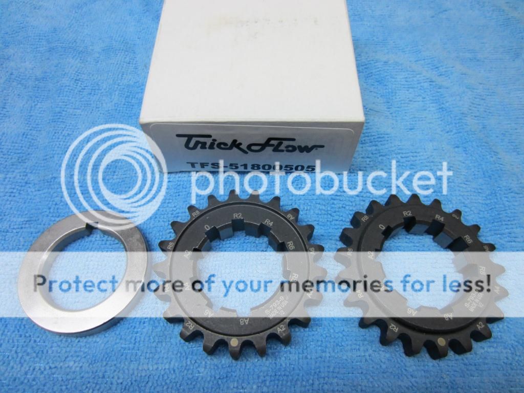
Adjustable Cam gears, As much as you guys hate BBR. Their cam gears are the best on the market, they will allow you to set timing exact. The only other alternatives I know are the TFS adjustable lower gears, the only allow adjustment in 2 degree increments. The other option is the Paschal performance and I would never use those, many people have had them come loose and end up damaging valve train. Here is a photo of the BBR units and them installed on my last motor.


Last, the base of my dial indicator contraption is magnetic. Since heads are aluminum I needed a steel base. I found a piece of steel plate, I drilled a hole and mounted it to the head and then attached dial indicator. It is important that you be able to set up the dial indicator at exactly 90 degrees from the deck of the head.

This covers the materials needed so lets begin:
The first step is going to be finding TDC(Top Dead Center), I turned the motor to where the piston was at BDT(Bottom Dead Center). I inserted the piston stop and turned the motor until the piston made contact with the piston stop. I then took the crank bolt and put the degree wheel on and set this up as 0 degrees.

Now you need to rotate the engine in opposite direction until you make contact between piston and pistons stop.

You can see, I landed at 55 degrees. Divide 55 degrees by 2 and this is TDC. In this case it is 27.5 degrees, I pulled the piston stop out and turned motor until I reached 27.5 degrees. I then loosened the bolt holding degree wheel and set it at 0, you at now at TDC.

TDC
I will now rotate the engine until I go .050 past peak lift, write this number down. As you can see I landed at 156.5

As you can see, the dial indicator is past .050. While it might not look like much, this is close to 1.5 degrees on the degree wheel. You really should be precise when Degreeing cams. The above picture was taken after I snapped this picture and noticed I was a **** hair past .050.

I will now rotate the motor back to .150 past the peak lift, the reason I did this is because I notice a little slack in chains when going back. After going back .150, I went to .050 before peak lift. Once again, write this number down. I ended up with 81.5 degrees.

Add both these numbers, divide by 2 and this is your intake centerline. In my case, 156.5 + 81.5= 238/2= 119. I want to set my intake centerline at 114 degrees, this means I need to retard the cams 4 degrees. I am not going to show how to do this because depending on what you use to degree the process will be different.
After you make your adjustments, you need to repeat the steps to find intake centerline and make changes until you reach the desired intake centerline.
I started with the drivers side because it is the chain that is closest to the oil pump, I triple check everything along the way and this process took me about 2.5 hours. I expect the passengers side to take about the same and then I will clean everything up and reassemble with all the followers. I have the Ford tool to remove and install rockers(Thanks Rojizostang) , I had trouble using it to remove the followers and just ended up unbolting cam caps and taking followers out. I do not know if this is due to custom springs and retainers or human error, Rojizostang is going to try and swing by and we will see if its human error. I do not want to have to lay followers on cams and tighten down caps to assemble the heads. I hope to have the long block assembled this week and add to this thread if I find other issues.
Thanks
Buzz
First is a list of items you are going to need. I made some of mine, Im sure you can buy them but I did it with items we had laying around the shop. This is my 2nd time setting up cams on a 3V, the 1st time I did it with my buddy Tim Lee@Maximium Velocity in San Antonio,TX. This time I feel comfortable enough to tackle it on my own
1) Dial indicator with adjustable arms to set up at 90 degree angle from deck of head.
2) Degree wheel
3) Pointer for degree wheel
4) Solid Lifter
5) Piston Stop
6) Crank Bolt
7) Adjustable Cam gears
Here you can see where I got a old spark plug, broke the top and center out and welded a dowel to make a piston stop.
Again, keeping it simple. I got a old lifter, fully extended it and tack welded to creat a solid lifter.
Homemade pointer
Crankbolt, I took my stock crankbolt and cut about ½ “ and used a spacer laying around the shop. This will hold the degree wheel to the crankshaft to take measurements.
Adjustable Cam gears, As much as you guys hate BBR. Their cam gears are the best on the market, they will allow you to set timing exact. The only other alternatives I know are the TFS adjustable lower gears, the only allow adjustment in 2 degree increments. The other option is the Paschal performance and I would never use those, many people have had them come loose and end up damaging valve train. Here is a photo of the BBR units and them installed on my last motor.
Last, the base of my dial indicator contraption is magnetic. Since heads are aluminum I needed a steel base. I found a piece of steel plate, I drilled a hole and mounted it to the head and then attached dial indicator. It is important that you be able to set up the dial indicator at exactly 90 degrees from the deck of the head.
This covers the materials needed so lets begin:
The first step is going to be finding TDC(Top Dead Center), I turned the motor to where the piston was at BDT(Bottom Dead Center). I inserted the piston stop and turned the motor until the piston made contact with the piston stop. I then took the crank bolt and put the degree wheel on and set this up as 0 degrees.
Now you need to rotate the engine in opposite direction until you make contact between piston and pistons stop.
You can see, I landed at 55 degrees. Divide 55 degrees by 2 and this is TDC. In this case it is 27.5 degrees, I pulled the piston stop out and turned motor until I reached 27.5 degrees. I then loosened the bolt holding degree wheel and set it at 0, you at now at TDC.
TDC
I will now rotate the engine until I go .050 past peak lift, write this number down. As you can see I landed at 156.5
As you can see, the dial indicator is past .050. While it might not look like much, this is close to 1.5 degrees on the degree wheel. You really should be precise when Degreeing cams. The above picture was taken after I snapped this picture and noticed I was a **** hair past .050.
I will now rotate the motor back to .150 past the peak lift, the reason I did this is because I notice a little slack in chains when going back. After going back .150, I went to .050 before peak lift. Once again, write this number down. I ended up with 81.5 degrees.
Add both these numbers, divide by 2 and this is your intake centerline. In my case, 156.5 + 81.5= 238/2= 119. I want to set my intake centerline at 114 degrees, this means I need to retard the cams 4 degrees. I am not going to show how to do this because depending on what you use to degree the process will be different.
After you make your adjustments, you need to repeat the steps to find intake centerline and make changes until you reach the desired intake centerline.
I started with the drivers side because it is the chain that is closest to the oil pump, I triple check everything along the way and this process took me about 2.5 hours. I expect the passengers side to take about the same and then I will clean everything up and reassemble with all the followers. I have the Ford tool to remove and install rockers(Thanks Rojizostang) , I had trouble using it to remove the followers and just ended up unbolting cam caps and taking followers out. I do not know if this is due to custom springs and retainers or human error, Rojizostang is going to try and swing by and we will see if its human error. I do not want to have to lay followers on cams and tighten down caps to assemble the heads. I hope to have the long block assembled this week and add to this thread if I find other issues.
Thanks
Buzz
Last edited: