
I cut them down, more than half is cut off, something like 40% of the the original height remains. Then I ground down the top to make it cone shaped so it still has a progressive rate. Plus I used bump stop relocation brackets to move them more forward so it has more vertical clearance. The rear end really has a lot of potential travel.
You are using an out of date browser. It may not display this or other websites correctly.
You should upgrade or use an alternative browser.
You should upgrade or use an alternative browser.
Help me choose a suspension setup
- Thread starter Screamin_dutch
- Start date
JJ427R
Senior Member
- Joined
- Jan 14, 2015
- Posts
- 3,305
- Reaction score
- 1,211
47, I as well have the Roush suspension, which lowers the car 1", and obviously suspension/spring rate is going to make a difference in how the car handles with these. Your springs are obviously way different, I'm not sure what the Roush are rated in lbs, compared to yours. I'm also not sure of what the difference would be with just the jacking rails as I have the Matrix Brace as well. Like Pentalab stated, it's kind of an apples to oranges comparison. On my car as well as Pentalab we noticed considerable difference in handling.
And yes with my 10 years of experience I'd love to compete against you on the track if you want to come to Road America or Brainerd. I'll be at RA July 5-7.
And yes with my 10 years of experience I'd love to compete against you on the track if you want to come to Road America or Brainerd. I'll be at RA July 5-7.
Norm Peterson
corner barstool sitter
My point was that if you're looking at the car's orientation against an imagined true vertical, 2° true roll because the road is cambering 2° out from underneath the inside will look like 0°. Tends to be misleading if you're not paying attention to the actual ground contour.If the road or track is cambered by say 2 degs to the inside, that can be factored into the equation. Either drive through it real slow, or stop every few feet, take measurements, then either factor it in.... or simply use the 'zero out' feature. Ok, say it is a consistent 2 degs..and we then zero the reading out. Take the corner at speed, and at 1G, it should read aprx + 2.0 degs. Or don't zero it out, then it should indicate...0.0 degs. Moot point really.
Perceptions can be misleading. I'm not trying to claim the you and JJ aren't noticing anything, only that you're not assigning crediting where it belongs.Norm, your calcs / software/ analysis may be on track / correct, but it still does not explain the effect that both myself and jj427r are seeing. This is not some subtle difference either, blatantly obvious that something somewhere has changed.
"I suspect that any increase in stiffness (esp torsional) may well enhance the effect of the front sway bar."
No. Increasing chassis stiffness does not change the front sta-bar from being responsible only for your left front corner to the whole left side. But for it to suddenly take over the entire left side's load transfer that's resisted by the bars, you'd have to disconnect the rear bar. And then you'd be seeing more roll rather than less.Norm, your comments above is what I was alluding to. With the jacking rails installed, and say taking a sharp left hander, the front sway bar now has the entire left side of the car to contend with....and not just the left front portion.
In actuality, the front bar is only providing one of the resistances to body roll, and the way load distribution works is that it divides up according to the relative stiffnesses. It's a springs in series/springs in parallel situation, where the stiffness of a reasonably stiff chassis plays only a minor role.
I really don't want to get into finding areas and torsional resistances when the S197's basic chassis really doesn't leave much flexibility for them to help resist. Compared to the existing S197 main structure, these are small elements in a secondary structural role.In my case, the front ends of each steeda jacking rail has a flat plate welded to it, with the flat plate facing inboard....(90 degs to the 2" x 1" CM jacking rails)
The stiffness that they do add is far more effective at changing structural vibrations, which is something that does lead itself to being felt. It should make sense that a car that feels more solid is one you trust better and are more readily willing to drive harder.
It takes more than the simple fact that they're present. It's how much additional stiffness they provide compared to the basic S197 chassis stiffness that really matters. It's the numbers that matter here, not the words.Point here is, in my case, with the recent addition of the pair of steeda jacking rails, it's now one continuous brace...from eng cross brace... straight back to the front end... of each rear LCA mount.
The addition of the CM jacking rails appears to be the final missing piece of the puzzle.... now tying the rigid front end....to the rigid back end of the car. The entire affair is pretty damned rigid. You folks can call it placebo effect, confirmation bias, pseudo junk science, or anything else you care to. [/QUOTE]
Stop. Just stop. I'm trying to teach something that I think I'm still reasonably qualified to talk about.
I'm sorry if I can't seem to find the approach that would really make this structural and mechanical engineering stuff 'click' for you. But if I didn't have a pretty firm grasp of the concepts myself, I wouldn't have been able to make an engineering career using them that spanned 42 years.
I am not among those who might be calling this a placebo effect or anything subject to confirmation bias. I'm looking at this in a strictly objective manner as far as the structural and mechanical effects are concerned. And I know a little about what makes for a more confident driver, or conversely that a driver whose car provides a less secure subjective feeling just isn't going to drive it quite as hard. It may not take much to go from less secure to more so.
Norm
Last edited:
Roush springs are only 20% stiffer than oem, maybe 150-165 range..and that's the fronts. Jacking rails are one thing, but the welded in, full length SFC's from BMR, or the kb's matrix brace is another level.
My fronts are still off the ground before the rears, if jacking in the middle.
Norm, I have no other logical /technical explanation for what I'm seeing. I've run out of ideas.
My fronts are still off the ground before the rears, if jacking in the middle.
Norm, I have no other logical /technical explanation for what I'm seeing. I've run out of ideas.
Last edited:
759-OR
Junior Member
47, thanks for the feedback on bumpstop. Tell me the purpose of the relo brackets. Were the stops missing the frame after you cut them short? And was that a custom piece you made?
I’m not wading into anything else here. My rails are one of my favorite accessories. Just because it makes service way easier.
;-)
I’m not wading into anything else here. My rails are one of my favorite accessories. Just because it makes service way easier.
;-)
47, thanks for the feedback on bumpstop. Tell me the purpose of the relo brackets.
As far as I know Vorshalg is currently the only one making them. https://vorshlag-store.com/collecti...ts/s197-mustang-axle-bump-stop-relocation-kit The intended purpose is so that you can cut off the chassis bracket to fit wider tires. But they also move the bumpstop forward so it hits higher in the A frame above it. I was originally going to make them, since its just a plate, but I happened across a set for half price and just bought them instead.
SteedaRacer47, what brand of jacking rails did you install ?
How is it possible for these to add enough chassis stiffness to be noticeable? All it is, is a filler tube that extends just below the pinch weld to make it easier to jack on. The front plate is even all cut up for the steeda logo. The rear bolts are on another plate. The actual square tube is not rigidly mounted to the car, just the plates at the ends.


Norm Peterson
corner barstool sitter
Belated appreciation for your comments, Racer.
This topic may have me revisiting one or two formulas in the spreadsheet I've been using. I expect only minor changes will result, none of which will reduce the average amount of body roll but will probably make the calculated amount of chassis twist a little more sensitive to changes in torsional stiffness. Won't be overnight, though.
These rails probably do a better job of increasing the bending stiffness of the main chassis rails along the door opening than anything. Your seats would be benefitting from slightly firmer support at least at the outboard seat mounts, and I'm pretty sure by enough to feel.
Norm
View attachment 69605 This is the weak spot. How can these 3 tiny areas of metal do anything for chassis stiffness?
Those end plates just hold the 2" x 1" rect tube in place. In my case, I had previously installed the steeda tq box triangular braces yrs ago, bolted and welded into place. ( https://www.steeda.com/steeda-mustang-frame-rail-torque-box-brace-555-5551.html ). The aft end plates of the steeda jacking rails slide between the upside down channel steel, that forms the 3rd corner of the triangle..and the under-body. I only welded corners #1 + #2 yrs ago. Damned good thing I didn't weld corner #3 at the time, or there would be no way to slide the aft end of the steeda jacking rail plate in there. I would have had to cut it off in the bandsaw...then welded the aft end of the steeda 2" x 1" jacking rails.
With just the pair of bolted in steeda jacking rails by themselves, there is probably minimal increased chassis stiffness. But I added the rails...after the fact. Used in conjunction with the welded in tq box braces, I could tell the difference right after the install, something sure as heck changed overnight. I'm still not done with it. The plan is to weld each 2x1 jacking rail in 4-5 places along it's entire length, on the inboard side of course.
Steeda shoulda just made the rails full length, but they made em shorter, to be used in conjunction with their existing tq box braces. That combo works pretty good, but still pales in comparison to a pair of BMR full length, dual rails, which requires a lot of welding....ditto with the KB matrix brace. For serious track
applications, the BMR / KB would be ideal, albeit more weight / expense /sanding / grinding / welding required. http://m.bmrsuspension.com/?page=products&productid=191 https://www.bmrsuspension.com/siteart/install/SFC011.pdf
eighty6gt
Senior Member
- Joined
- May 9, 2011
- Posts
- 4,306
- Reaction score
- 416
nothing I like better than visiting threads like this watching people add to the mass of their car and subtract from the mass of their wallet. It's like that time I bought a $700 throttle body!
Norm Peterson
corner barstool sitter
For serious track applications you really should go with a cage instead. Or possibly a cage in addition to some sort of undercar bracing.For serious track
applications,
Norm
Vorshlag-Fair
Official Site Vendor
Very good observation!View attachment 69605 This is the weak spot. How can these 3 tiny areas of metal do anything for chassis stiffness?
The hubris is amazing - when companies spend a lot of time to cut their logo completely through critical load paths on parts that supposedly "add stiffness" or otherwise have high loads going through them. I've seen control arms fail - at the logo. This silly part will fail - at the logo.
"Luckily" this is just another "steelitus" upgrade, where you "throw steel at the car" to fix some perceived problem, but it does nothing but lighten the wallet.
")
Stay skeptical, people!
I agree. The laser cut logo is a dumb idea.....(but good enough for jacking purposes, and to say it's a... 'bolt in mod'). For a more robust install, the 2x1 rect tubing itself should be welded in 3 places. Each end ......(and the middle, where steeda welded in a 2x2 re-enforcing / backing plate).
For folks that have the steeda trunk mount 'X' brace, it too requires welding.... on all 4 x corners of the 'X'....esp the bottom corners. Unless the bottom 2 x corners are welded, (where they sit over top of the rear shocks, directly on the shock towers), they are doing nothing. As is installed per steeda directions, the tops are bolted, with 2 x 12mm bolts each, and each 3rd top hole is used for optional welding...for more rigidity. They don't mention anything about welding the bottom 2 x corners. As is, they are only held down by the nuts + rubber grommets. Fortunately, there is no logo on any of the 4 x corners.
For folks that have the steeda trunk mount 'X' brace, it too requires welding.... on all 4 x corners of the 'X'....esp the bottom corners. Unless the bottom 2 x corners are welded, (where they sit over top of the rear shocks, directly on the shock towers), they are doing nothing. As is installed per steeda directions, the tops are bolted, with 2 x 12mm bolts each, and each 3rd top hole is used for optional welding...for more rigidity. They don't mention anything about welding the bottom 2 x corners. As is, they are only held down by the nuts + rubber grommets. Fortunately, there is no logo on any of the 4 x corners.
Last edited:
Norm Peterson
corner barstool sitter
I'm not a fan of cutting a logo where strength is needed. Not at all.
Though I do understand a vendor adding something to his design to discourage unauthorized parts reproduction, which I'm pretty sure the logo was intended to accomplish.
Norm
Though I do understand a vendor adding something to his design to discourage unauthorized parts reproduction, which I'm pretty sure the logo was intended to accomplish.
Norm
oldVOR
Senior Member
Can you tell me how your handled your rear bump stops with that setup?
I have the FRPP units with the tops cut off. But wanted to see how others were handling that.
It seems you have probably experimented and thought it through.
Thx
759-OR for the DIY'er What have you done to your mustang today?
Vorshlag-Fair
Official Site Vendor
4Tell me the purpose of the relo brackets. Were the stops missing the frame after you cut them short?
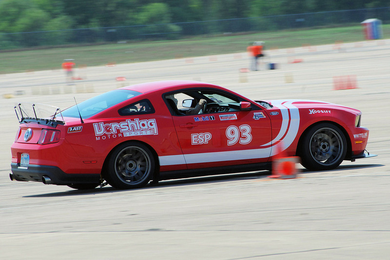
Most people do not need to relocated the rear bump stop bracket. We did this on our Mustang (and many since) to make room for an 18x12" rear wheel, which we ran from 2012 through the end of of 2015 when we sold the car. Our unique wheel offsets allowed us to fit this massive rear wheel under the stock fenders using a 315/30/18 Hoosier, as shown above. We ran an 18x11" on the same sized Hoosier up front, also under stock fenders. Those were both "max fitment" race wheel setups under stock fenders.
This 18x12" rear doesn't just "bolt up" without any modifications, of course. For 95% of the customers that want "max fitment" wheels on the S197 under stock fenders we supply an 18x11" rear instead. Even those still need an adj Panhard Rod or Watts Link to make sure the axle is perfectly centered.
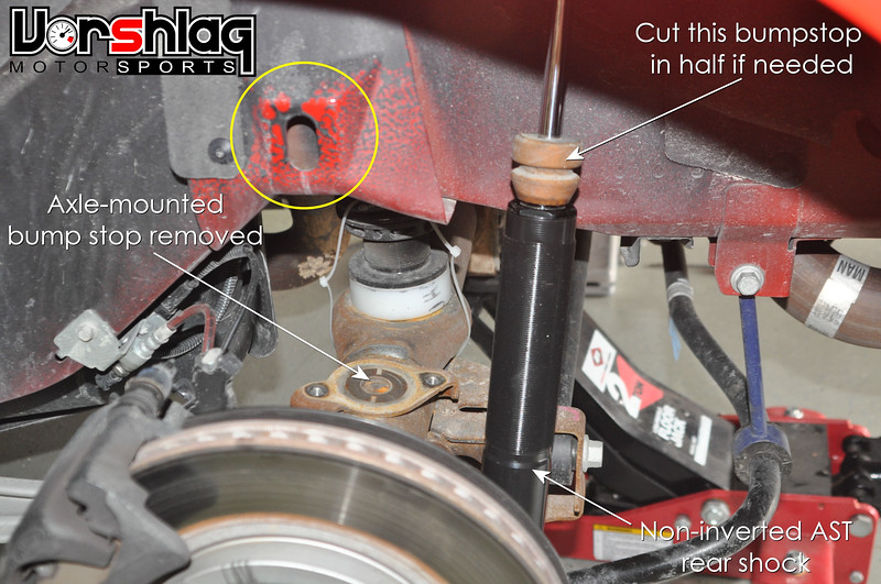
Ignore the AST shocks above - we quit selling those in 2012 - but the pic has good labels on all of the bits we are talking about. For that more dedicated 5% that wants every inch of wheel possible, we warn them that the inner barrel of our 18x12" wheel will "hang" on the upper tie-down hook/bump stop landing plate shown in the yellow circle above. Not a huge deal, never happens when driving, but it will hang up when you have the car in the air on a lift with the rear suspension at "full droop". To remove the wheels when the car is on a lift you have to put a jack under the axle pumpkin to raise it up enough to "un-hang" the 18x12" wheel barrel. This is annoying, but we have a way to remove that protruding section of sheet metal, shown below.
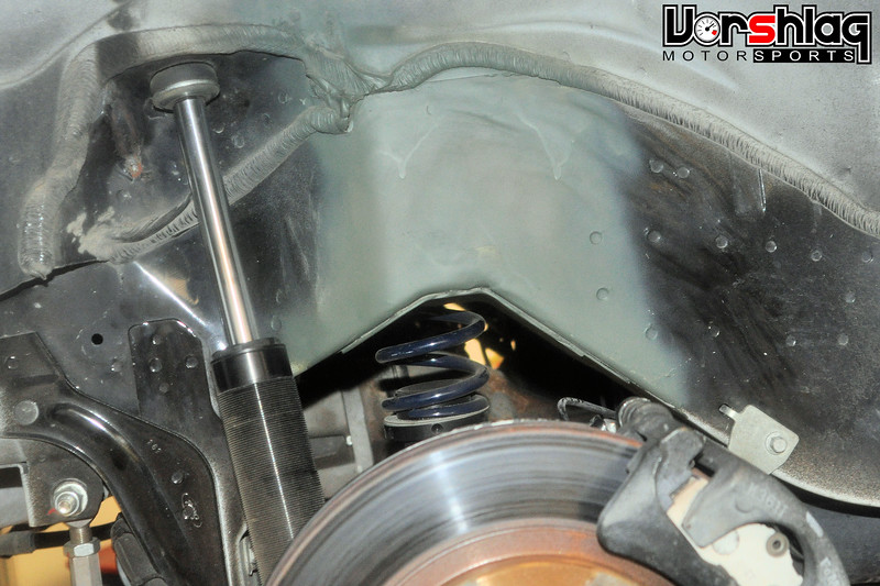
After marking and center-punching about 12 spot welds, these are each drilled out with a spot weld cutter. Then this stamped sheet metal upper bracket can be removed, and our 18x12" wheel can fit at full droop without interference. Some folks leave the lower section (that follows the curve of the frame rail), to have some additional strength there - just cut it off at the corner and leave that lower bit spot welded on. We spray all of the bare metal exposed by removing this bracket with "self-etching zinc primer", which is often this drab green color. You can cover that with prettier paint if you like.
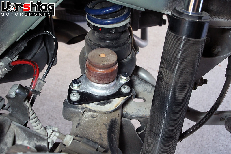
Of course when you remove that upper bracket, the axle mounted bump stop no longer has an upper contact plate - which is needed to prevent "over travel" of the rear shocks under an extreme rear bump travel situations. So we developed this S197 rear bump stop relocation bracket kit, shown installed above. We always cut that bump stop in half on lowered cars, by the way.
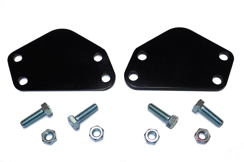
This kit consists of two CNC cut pieces of steel plate, powder coated black, and the hardware to mount the bump stop to the bracket, which moves the bump stop inboard by over 1/2", to line up with the beefy flat portion of the rear frame rail. The two stock bolts and captive nuts on the axle are re-used to mount the bracket to the axle. Simple, no welding required, and the first few we hand made have been in use for 7+ years without issue. We started selling production cut versions of these last year and have sold dozens - which we make in-house on our CNC plasma table, so we can't run out of stock.
Cheers,
Last edited:
Vorshlag-Fair
Official Site Vendor
Wait, you want me to give data to counter your non-data opinion?To Terry Fair, I would like to see any data you may have that says an X-Brace or Matrix brace will not help the performance of the car, especially in cornering on the track. I completely disagree with your comment on that as I will explain below.
Yikes, you are using "believe" in one sentence (opinion) and "will make car stiffer" in another (with zero data to back up this measurable claim).I don't see above where I said these items and stiffening up the chassis would give a better ride, I said it would give better cornering, which I truly believe they do, as I have run on the track with and without these items and I do notice a difference. A Matrix Brace will make the car stiffer and actually make the ride a bit rougher, won't give a better ride.
There are scientific ways to measure torsional rigidity on a chassis. If you or these companies want to claim these doo-dads actually make a measurable difference, the burden of proof is on you/them. And even when you do this torsional rigidity test, that still does NOT translate into lap times. That's a much more complicated test with MANY more variables. See below.
Wow. 2 second drop with some doo-dad bracing. That is such a bold and outrageous claim that I don't even know where to begin.I cut my lap times at BIR on the 2.5 mile track by 2 seconds in my 2010 Mustang after I added the Matrix brace/Jacking rails and doing nothing else to the car, even same set of tires. Was it my driving improving that much? I doubt it as I drive one handed with hand controls, so I feel quite justified in my own personal data.
Look, most of us here are amateurs and I suspect a majority of users don't even have accurate lap timing equipment beyond a free phone app. The track condition differences day to day can be huge, and I've seen 2 second changes IN THE SAME DAY just from rising track temps. Now let's factor in tire age/compound heat cycle differences, DRIVING differences, traffic differences, and other conditions and your 2 second change can get swallowed in the vast sea of potential change.
Do a double blind, scientifically controlled, A-B-A (such as on-off-on) for your doo-dad using a proven consistent driver, on the same day, with fresh tires and the same track temps, and zero traffic. If you cannot bust off laps within 0.1 to 0.2 sec lap after lap your test is already invalidated.
Also look up the term: confirmation bias
Fully 75% of all posts on forums seem to be people "asking questions" to confirm the parts choices they have already made.
Just keepin it real...
Norm Peterson
corner barstool sitter
"will make car stiffer"
Terry, I've got over 50 posts in this thread centered on clearing up misunderstandings on just those two points. I actually made some driveway measurements regarding the first (and posted what I found starting at around post #120). On the latter, I'm afraid that there are people who underrate the matter of "driver confidence", particularly when said driver only gets out on the track occasionally. There could be other factors at play here, but I'm not going to speculate any further than that.2 second drop with some doo-dad bracing.
Norm
JJ427R
Senior Member
- Joined
- Jan 14, 2015
- Posts
- 3,305
- Reaction score
- 1,211
Do a double blind, scientifically controlled, A-B-A (such as on-off-on) for your doo-dad using a proven consistent driver, on the same day, with fresh tires and the same track temps, and zero traffic. If you cannot bust off laps within 0.1 to 0.2 sec lap after lap your test is already invalidated.
I don't need scientific data to know how a car feels when I'm driving it, and I get what you are saying about lap times changing from day to day and even the same day, been there done that. I've only been driving on the track for 8 years, but I have quite an understanding of cars and driving on track.
I have several instructor friends at BIR's Performance Driving School, of which one currently drives in the Trans Am Series, and he has driven my car on track and was quite impressed how well my car cornered compared to other Mustang he has driven, of which he has driven many. That is all the confirmation I need.
I believe (on my, I used that word again) Kenny Brown of Kenny Brown Performance, company who made the Matrix brace I have, as well as his late son Paul Brown, have many championship wins a well.... and I'm betting they have the data to show if it works or not. You should probably contact them.
Similar threads
- Replies
- 36
- Views
- 3K
- Replies
- 6
- Views
- 587
- Replies
- 6
- Views
- 1K
Latest posts
-

-
-
-
Should I stay away from 2005 to 2008 (spark plugs)?
- Latest: 2019Chieftain-no-more
-

Support us!
Support Us - Become A Supporting Member Today!
Click Here For Details