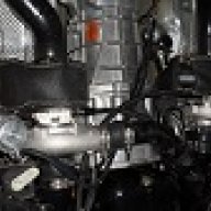
Installation and Q&A for S&H Stealth Twin kit 05-10

TexasBlownV8

Formerly TexasBlownV6
Joined
Apr 4, 2008
Posts
5,025
Reaction score
101
Location
Central Texas
I have a couple of questions regarding the cooling lines/hoses.
1) although not part of a simple bolt-on/stock-engine setup, any thoughts on drilling/tapping the passenger side outlet of the coolant crossover, and using a 3/8 npt to -an fitting there, in the large boss area on the crossover? (I'm planning on doing this instead of using the inline radiator hose couple/adapter).

2) regarding the hose sizes, each turbo gets -6an in and out for cooling, splitting off and joining back from/to a -6 Y coupler. Any reason why not go with -8 to/from the Y's, and -6 to/from the turbines? I would think it would be a more efficient and adequate coolant flow. (I'm considering using -8 from the block to a Y, and then using -8 on the return, back to the crossover as noted above. The individual lines to/from the turbos would still be -6an).

 

JeremyH

3V Fuel Guru
Joined
Jan 10, 2009
Posts
20,857
Reaction score
208
Location
Virginia Beach
I have a couple of questions regarding the cooling lines/hoses.
1) although not part of a simple bolt-on/stock-engine setup, any thoughts on drilling/tapping the passenger side outlet of the coolant crossover, and using a 3/8 npt to -an fitting there, in the large boss area on the crossover? (I'm planning on doing this instead of using the inline radiator hose couple/adapter).

2) regarding the hose sizes, each turbo gets -6an in and out for cooling, splitting off and joining back from/to a -6 Y coupler. Any reason why not go with -8 to/from the Y's, and -6 to/from the turbines? I would think it would be a more efficient and adequate coolant flow. (I'm considering using -8 from the block to a Y, and then using -8 on the return, back to the crossover as noted above. The individual lines to/from the turbos would still be -6an).


Yes you could drill and tap the passenger side crossover. You can also return to the coolant expansion tank or weld a bung and return to the top of the radiator on the passenger side as well. The splice in adaptor provides the easiest means for the average setup and thats why we include it in the kit.

The turbos actually need very little flow to cool. I discussed using a 8an line with Comp and they expressed that there was no need. Increasing to 8an just on the supply line before the Y to 6an split and then 6an feeds would actually not increase flow anyway, as the smallest fitting diameter will determine flow at that given pressure. The freeze plug size for feed on the side of the block is 3/8npt, that size for feed and water jacket size in the chra of the turbos determines this flow at your water pumps output pressure of 10-13psi. So you could use 8an, 10an, 12an lines in the system and it would not increase flow. It actually may decrease flow a little through the chra as pressure would go up some by having larger lines before and then collapsing it down, its a closed loop system so the water will take the path of least resistance. To summarize 6an lines are perfect and what is recommended by Comp and what we use with no issues. I'm even using 6an T fittings for supply split and return merge on my car, that's how unimportant needing a bunch of flow is, we supply Y's in the kit though to help optimize everything. No need to go larger unless you just want to.
 
Last edited:

TexasBlownV8

Formerly TexasBlownV6
Joined
Apr 4, 2008
Posts
5,025
Reaction score
101
Location
Central Texas
Can you elaborate more about the vacuum lines, especially as they need to be run for the wastegates and BOV? Is there a recommended configuration, or something both of you have used?
Allow me to break it down as I see it; here are the 'things' that need vacuum fed to them:
- brake booster
- fuel rail pressure sensor
- evap solenoid (assume it is still being used)
- BOV
- wastegates

Using a stock intake manifold, there are 3 vacuum/boost ports.
- the back port is typically used for the brake booster and FRPS
- the smaller one up front is typically used for evap
- the large one up front is typically used for crankcase ventilaltion

I typically try to use a dedicated vacuum port for anything heavy or important, such as the BOV.
Various documentation about the wastegates recommend referencing the pressure side of air flow before the throttle body.

As such, with the BOV in place, does it make logical sense to provide the wastegate vacuum reference before the BOV? Or, as noted elsewhere, after or in the i/c?

Each turbo housing has a place on the outlet housing where a hole can be drilled and tapped and a fitting put in, and that would provide an accurate nearby pressure reference to the appropriate wastegate. Would this be the preferred way to hook it up? Or, would it make more sense to use the combined boost pressure from both sides, after they've combined into the single air pipe, where both wastegates would be fed the same pressure reference back to them? If done before the BOV, the actual built-up pressures would seem to be more accurate than after the BOV, where some of the air will be vented out.
 

Timmbo

Senior Member
Joined
Jan 17, 2011
Posts
2,067
Reaction score
0
Location
TN
Get yourself a nice Fore vacuum block. It will eliminate a lot of "t" joints and keep things neat. Love mine.

31-100-5.jpg
 

JeremyH

3V Fuel Guru
Joined
Jan 10, 2009
Posts
20,857
Reaction score
208
Location
Virginia Beach
Like timmbo mentioned I run the Fore vacuum block as well off the brake booster line at the firewall and love it, we can get you hooked up with one just let me know. I like to have dedicated sources for this stuff as well and this the best solution compared to running T's etc.

20121004_201814.jpg
 
Last edited:

TexasBlownV8

Formerly TexasBlownV6
Joined
Apr 4, 2008
Posts
5,025
Reaction score
101
Location
Central Texas
..that doesn't really answer my questions...but great answers follow in the posts below..so read on!
:hi:
 
Last edited:

JeremyH

3V Fuel Guru
Joined
Jan 10, 2009
Posts
20,857
Reaction score
208
Location
Virginia Beach
Edit: you jumped the gun see below lol


Now about vac/pressure sources.

BOV has to be a boost and vacuum source on the engine side of the throttle body to function properly ie (intake manifold source, brake booster line frps line, evap return port on the manifold if you have evap deleted etc. These instructions are explained in post #2 as well.


Waste gate source is up for debate and can be done different ways. The ideal source for proper response is a pressure only source on the turbo/charge piping side of the throttle body, closer to the turbo the better. Common choices are drill and tap the turbo compressor cover, a fitting on the charge piping at the outlet of the turbo, on the intercooler itself. (or outlet side of intercooler which falls into the next method slightly.) This pressure only method will measure pressure at/near the turbo so say your gates have 10psi springs, you may only see 7-8psi at the intake manifold due to volume loss in the pping and pressure drop across the intercooler core. This methods big advatange other than faster wastegate response and control is that if you develop a cold side leak between the turbo and throttle body, you will know right away and not damage the turbo. ie You hear the turbos spool and wastegates open (limits shaft rpm) but your not registering any boost on your boost guage that's off the intake manifold. You know right away you have a coldside leak or a coupler that slipped apart etc. And there is no risk to the turbos. A downfall (if you call it that) to this method is you will get boost sag in the upper rpms ie boost will taper off some although hp and tq remain as flow stays up. Some guys don't like this boost sag on their boost graph though.

The other way is use a boost vac source just like the bov uses. This method will get you absolute pressure of the wastegate springs at the manifold if not more. ie 10psi springs in the wastegate you will no shit see 10-11psi at the manifold since the wastegates aren't fully opening until this same pressure source is applied. The downfall to this method is if you develop that coldside leak, the wastegates wont know it since its not getting the pressure at the manifold to send the signal to open the gates. One good high rpm blast with a good leak and gates never opening can serious damage to the turbos from overspinning the shit out of them as they will just keep spooling up and dumping that pressure before it ever gets to the intake manifold. One perk guys like about this method is there is no boost sag in the upper rpms the turbo will continue to spin up slightly as the rpms rise to maintain that pressure as flow though the motor goes up, you often see little pressure spikes up top as well using this method.

I have use both methods, both have worked well for me, I would say the second method would be for the guy who is very in tune with his setup and knows what to expect.

The instructions are a bit vague on purpose as there are many different ways to do it so we don't say thall shall hook this up here. Hope that helps clear some things up and let me know if you have anymore questions.
 
Last edited:

Bobby

turbo gt about to go fast
Joined
Dec 10, 2007
Posts
5,085
Reaction score
2
Location
just out side of charlotte north carolina
I run everything from the bov to wastegates to the boost controller off my fore vacuum block. So it all sees boost/vacuum. I have bever had a problem with this. Also comp has guys making 80psi on a Diesel motors.
 
Last edited by a moderator:

JeremyH

3V Fuel Guru
Joined
Jan 10, 2009
Posts
20,857
Reaction score
208
Location
Virginia Beach
Waste gate setup, the things you mentioned are all feasible and would work, there are no kidding a dozen plus different ways to set it up. I will try to go over some.

First and simplest is boost/vac or pressure only source hooked directly to the side port of the gate and top port vented to atmosphere. This is will allow the gate to run just off installed spring pressure and is the minimum boost you can run. So if you install 5psi spring in the gate(s) you will see a around 5psi all day long depending on source. If you install 10psi spring you will se 10psi and so on.

Next is using a manual or electronic boost controller. There are many ways to do this as well. The most simplest would be to plumb your mbc or ebc solenoid in the line to the side port of the wastgate and leave the top port open to atmosphere. Using this method your minimum boost pressure will be installed spring pressure with the controller turned all the way down. So if you got 10psi springs in the gates you will see around 10psi. Now as you dial your controller up you can runner higher than spring pressure so you can dial it to run 11, 12,13,14,15psi and so fourth up to about double spring pressure effectively so if you have 10psi springs in the gates and you turn your controller all the way up you will see a max of roughly 20psi.

There are alternate methods using split ports, dual ports T fittings between ports etc yo get different kinds of boost responses. The link below has some diagrams showing a lot of these methods. See pages 8 through 13 on e-Boost2 (2005-current) – Complete User Manual

Here is the link. If you don't intend to run a boost controller substitute the solenoid in the diagram as your pressure/vac source.

http://www.turbosmartusa.com/instructions-downloads
 
Last edited:

JeremyH

3V Fuel Guru
Joined
Jan 10, 2009
Posts
20,857
Reaction score
208
Location
Virginia Beach
Here is a diagram of how my car is currently setup. Using an electronic boost controller.


wg1_zpsca1f7762.png


Here is one way to use no controller and just run off spring pressure in the gates using one turbo for pressure only reference.

wg2_zps02e8a3bf.png


And again using both turbos to equalize pressure from each side and then go to the gates.

wg3_zpsac265e5a.png
 
Last edited:

JeremyH

3V Fuel Guru
Joined
Jan 10, 2009
Posts
20,857
Reaction score
208
Location
Virginia Beach
K member clearance.

This pic I had already trimmed some off the top of inside a-arm mount and then shows what needs removed off the k member.
kmemberbefore_zps069774d5.jpg


And here is after K member trimmed.

kmemberafter_zps61f18559.jpg
 
Last edited:

Latest posts

Support us!

Support Us - Become A Supporting Member Today!

Click Here For Details

Back
Top