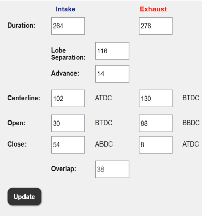
Lunati VooDoo #21270700 Camshafts

GlassTop09

Senior Member
Joined
May 24, 2019
Posts
1,145
Reaction score
526
Location
Farmington, NM
Congratulations.

It would be great for you to document the cam install. Maybe turn it into a sticky for future users.
Ok, I'll assume you're referring to the tuning side of these Hot Rod cams "install", yes?

As far as the physical install of them in the engine, this is std affair.........when I do it, I strictly follow the Ford Racing Hot Rod cam installation instructions they give out w\ these cams. I used their instructions (along w\ a timing wedge tool & a spring compressor tool) as a guide to install my Lunati's back in June 2019 w\o issue.
I know others here just unbolt the cam caps evenly to slowly unload\reload the valve spring tension to not use the spring compressor.........more power to them but I'm not gonna go that route (there are specific reasons why removing the specified cam followers is included in the instructions to unload the cams when they're rolled to the 7 o'clock--or 180*--position so I'll stick to them) so outside of this, the rest is academic. Plenty of coverage on YouTube to use to assist w\ removal\installation.

Outside of this, when I do it, I'll post my findings\final setup as usual.............

Appreciate your words of support!

:beer:
 

JC SSP

Senior Member
Joined
Nov 8, 2022
Posts
1,079
Reaction score
466
Location
FL
I was really referring to the install as I know your an ace in the tuning and post all your tweaking.
 

GlassTop09

Senior Member
Joined
May 24, 2019
Posts
1,145
Reaction score
526
Location
Farmington, NM
FYI........................

I've been thinking about this Ford designed knock retard algorithm system incorporated into the SO OS's & I believe I've figured out the full design & intention of how Ford meant for all this to be used........some of it could be used in a different manner, but I now think that this was not their intentions........so here is my interpretation\understanding of this system's code path layout.

1st, the coding is located within the SO OS VID block & works in tandem w\ a dedicated onboard sound DSP type module to do all this sound processing\filtering of the voltage generation from the 2 KS mics to then pass the results to the main engine processor to act upon, the Octane Function "plug" setting in there serves 2 purposes..........1 I've typed out in full in post #471 concerning the Octane Adjust function......but the 2nd is full cyl knock detection.....this Octane Function plug setting is Ford's way of setting the cyl knock specific sound frequency of a specific fuel's AKI rating at the time it breaks down from heat & pressure into cyl knock (usually measured in MHz) so the 87,89,91,93 oct RON numbers represent in the Ford OS coding the MHZ frequency associated w\ cyl knock using the specific fuel octane. HPTuners VCM Suite, to my knowledge (I've asked for this info on the forums w\o a response to date.....even though they DO provide access to VID block enable\disable, axle gear ratio, tire size or revs per mi, OSS sensor tooth count selection, CANbus access from PCM or SCP thru their interface thus tune calibration file so can't see why not this Octane Function plug setting.....) doesn't provide access to any of this section of the VID block (as opposed to SCT in which they do......thru the Options selection in the X4 tuner under "Fuel Type") so at this time, if you still have an operational HPTuners NGauge tuner you can access the VID block & see this if needed......or Forscan w\ a J2534 interface to access 18v FEPs within the VID block & a license to unlock the module programming capabilities in Forscan.

Outside of this, the rest can be accessed thru the HPTuners interface thru the tune calibration files & edited in VCM Editor software..........

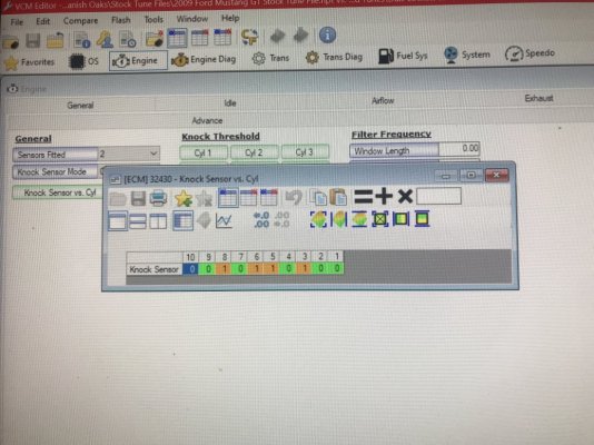
2nd, the KS mic to cyl assignment table is what determines which cyl is assigned to 1 of the 2 block-mounted KS mics to provide separate individual cyl knock detection........a step up from the 2V global knock detection system (uses only 1 KS mic to detect individual cyl knock thus can't differentiate 1 cyl's knock frequency from another so treated all sound frequencies the same) so individual cyl specific knock sensor sensitivity noise threshold mapping can now be used to differentiate 1 cyl's noise output from another cyl. To be able to properly calibrate these individual cyl noise floor maps, the system was set up to be switched in to Per Cyl Mode (normal operating mode is Global Mode) to allow individual cyl noise threshold tuning for knock sensor accuracy to each specific cyl. Now Per Cyl Mode can also be used as the primary cyl knock control for the engine (I was using this predominately for main knock retard control for the obvious advantage of the ability to control knock on an individual cyl basis to reduce the amount of HP\TQ loss thru a single cyl knock event\spark timing retard) but I realized later on after working w\ this that this most likely wasn't Ford's intent for Per Cyl Mode to be used for main knock control (there are some quirks in the software application that give some light to this.....namely cyls 1-4 draw out very irregular graph lines when knock is detected on any of these 4 cyls.....regardless of which KS mic they're assigned to while cyls 5-8 draw out very clean graph lines--regardless of the KS mic they're assigned to--that look like the clean graph lines drawn thru Global Mode.....IMHO appears to be some type of quirk in the ECU's sound DSP circuitry\software that is getting fed to the main processor concerning cyls 1-4 only......the cyl knock is detected OK, just isn't drawn out\graphed properly so it looks like the affected cyls are retarding\recovering spark differently from the other cyls but in reality they're not) but mainly for ECU onboard access to perform accurate individual cyl noise sensitivity threshold level tuning purposes for proper cyl knock detection\control only. Global Mode is the Ford intended main knock control for this 3V engine (the filtering up\down signal avg accel\decel settings are only applied to the detected KS mic voltage frequencies under Global Mode.....all else is used in both Global & Per Cyl Mode).

The found issues concerning the KS mic to cyl assignment I have well documented in several postings within this thread, but I believe was done intentional by Ford to provide an "extra" layer of "engine protection" to promote warranty claims (all 1st Gen Coyotes also use this intentional KS mic-to cyl assignment "fix" to do the exact same thing mentioned above thus negatively "influences" their rated HP\TQ FW outputs by excessively (meaning falsely here) cutting spark timing in return for increased engine safety\reliability. When the knock control is left in Global Mode, this control covers this up due to any spark retard getting applied to all 8 cyls so you can't see\tell which cyls are causing the cyl knock to occur........but now I know which ones are causing the false cyl knock due to me uncovering this.......#2 cyl & #6 cyl according to engine specific firing order.

Using the 3V's firing order of 1-3-7-2-6-5-4-8, when #7 cyl fires it sets a certain cyl sound frequency thru #0KS mic voltage based on the cyl's actual sound output & the distance between the #7 cyl & the #0 KS mic. #2 cyl fires next in 90* crank rotation but #2 cyl is assigned to the same #0 KS mic as #7 cyl AND it is much closer to the #0 KS mic than #7 cyl is so when #2 cyl is fired it will create a much higher sound frequency noise signal than #7 cyl did--not because #2 cyl firing created a higher initial sound frequency than #7 cyl, but because #2 cyl is located much closer to the #0 KS mic than #7 cyl, the #2 cyl sound frequency didn't get scrubbed travelling thru the engine block metal as much as #7 cyl so the #0 KS mic registers a higher noise spike that can exceed the filtering settings thus ECU thinks #2 cyl had a cyl knock event.....when in reality it didn't.....& cut spark timing erroneously. This same phenomenon is also occurring between #6 cyl & #5 cyl in reverse--w\ #6 cyl firing in succession to #2 cyl, these 2 cyls are located the exact same distance from their assigned KS mics (#2 cyl to #0 KS mic, #6 cyl to #1 KS mic) so when #6 cyl fires, its cyl noise signaling output to #1 KS mic is on the same level as #2 cyl was so no issue as the cyl noise frequency was well below the "newly created cyl knock noise floor" by both #2 & #6 cyls--but when #5 cyl fired, due to it being located much farther back from its assigned #1 KS mic (the same as #6 cyl) it recorded a much LOWER KS voltage signaling than #6 cyl did in the same manner as the #7 cyl to #2 cyl scenario created the HIGHER KS voltage signaling. A sound wave frequency is output as a sine wave--an up\down frequency vibrating pattern & is reflected in the KS mic voltage output due to the voltage being low level AC--alternating current--so this is also interpreted as a cyl knock if the filtering up\down avg on accel\decel vs not accel\decel can't wash it out so ECU thinks #5 cyl had a cyl knock event occur......when in reality it also didn't.......& cut spark timing erroneously as well thus you can have 2 cyls cause erroneous cyl knock to occur AND these 2 cyls will always show up thru Per Cyl Mode to be the 2 cyls that are always appearing to be "knocking" when they aren't while the rest are showing to be w\o knock.............but if left in Global Mode you'd never catch this causing 1 to erroneously adjust individual cyl noise sensitivity threshold mapping seriously desensitizing them & setting up catastrophic engine failure thus excessive engine knock in reality for absolutely no reason when the real issue is in the KS mic-to-cyl assignment between #2 & #6 cyls.....just need to switch them to the opposite KS mic than the 1 they're originally assigned to by Ford to "level out" the entire firing cyl noise floor to then match w\ all the other cyls that never exhibited any knock at all then all this will go away, then any cyl knock that does show up after this is fixed can then be seen as legit.......w\o touching any of the OEM Ford-tuned individual cyl noise sensitivity threshold map settings in tune calibration.

All the basic physics behind this I gave explanation of in post #476 in this thread......................

Took me some time to catch & figure this out (had actually "caught" it early on when I originally mapped this out to determine that my original KS mic harness had a failing #0 KS mic due to never seeing any cyls assigned to #0 KS mic showing any cyl knock while the #1 KS mic was showing plenty of cyl knock.......but it didn't click until much later on, after replacing the bad KS mic harness, when I was trying to determine why I only saw #2, #3, & #5 cyls consistently showing cyl knock while the rest were showing to be clean.....regardless of how much spark timing I would cut.....#3 cyl issue was lack of sufficient transient fueling to offset cyl knock when TB blades were swept closed\open during WOT shifts (leaned fueling out momentarily......this also affected #5 cyl as well thus #5 cyl knock looked far worse than what it really was due to the mentioned above assignment issue & #2 cyl knock was completely false) but #2 & #5 cyls were severely negatively affected by this erroneous KS mic to cyl assignment between #2 & #6 cyls...............

The key for me to get to this finding was from me bypassing Global Mode to use Per Cyl Mode so I could clearly see these affected cyls only while the rest were showing to be clean.......even when I replaced all the BAMA\prior tuner touched individual cyl knock noise sensitivity threshold maps w\ the OEM Ford-tuned maps......which then started me to check elsewhere besides these maps......then 1 morning while I was thinking about all this & looking at my original drawn "map" I made of this KS mic to cyl assignment according to engine firing order, the "light bulb" came on.........the rest is history.......

Posted for informational purposes & a physical record on this site for others to use.
 
Last edited:

crjackson

Member
Joined
Nov 28, 2015
Posts
609
Reaction score
308
Location
Midgard
Holy crap! Too late to read this tonight. I’ll try to start at 6AM and maybe I can finish up around midnight :lol:
 

GlassTop09

Senior Member
Joined
May 24, 2019
Posts
1,145
Reaction score
526
Location
Farmington, NM
FYI....................

Here's some more data I've compiled to further solidify what I've typed in post #483...........

From pg 20, post #398 in this thread:
Once I got the fueling sorted out, I then started cutting spark advance timing until I got clean KS spark advance 4* curves during WOT 1\4 mi runs.......ended up at 18.2* BKT\MBT max spark advance timing (BKT max spark advance timing + the 4* KS added spark advance timing will always agree with the MBT max spark advance timing since both BKT\MBT VCT spark advance adder maps use the exact same settings.......unless the BKT spark advance timing is corrected for ECT, IAT or lean Lambda.......the intentional 4* separation of all settings in base BKT spark advance timing map vs base MBT spark advance timing map sets the KS additional spark advance timing adder range thus this range is considered normal spark advance\retard operations)......this is the most spark advance timing I could run w\o creating excessive cyl knock during WOT 1\4 mi runs on clean E10 91 oct pump gas @ .84 Lambda (could add as much as 25* max spark advance timing using 8 oz of VP Racing Octanium Unleaded Octane Booster in same E10 91 oct pump gas w\o cyl knock.....proves how bad our E10 91 oct pump gas is in the Land of Enchantment).......which is a LONG WAY away from the 31.95*-32* of max BKT WOT spark advance timing that my prior tuner had set.........then hid the KS's from the PCM during WOT.........man, I'm glad I didn't beat on this thing @ WOT depending on the 4* max of knock spark timing retard prior tuner had put in his tune like I had to do street tuning WOT under my tuning (why I had the max knock retard timing map set @ -8* for a combined total of -12* retard from MBT max spark advance timing.....for safety purposes......it's STILL set for this right now)........would've certainly cost me an engine!
Note that the 18.2* total WOT timing I recorded to cut to get the WOT spark traces fully clean of any cyl knock on clean E10 91oct fuel.......was using the OEM cyl knock sensitivity threshold maps and the OEM KS mic to cyl assignment map data as well at the time (all provided in pictures below).

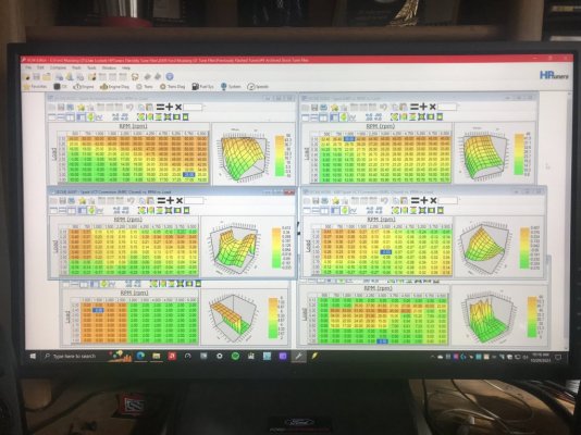
Now look at the Ford '09 OEM MBT Spark Advance timing map in upper right of 1st picture & make note of the total spark timing in .80 load row from 4,000 RPMs on that Ford tuned to during WOT.........using the exact same Ford OEM knock control cyl noise maps & KS mic to cyl assignment map settings..............now tell me, you think all this is just a coincidence of me just happening to hit the SAME WOT total spark advance as Ford did using their calibration knock control setup by Ford themselves?

Or just maybe......maybe......what I typed in post #483 is actually the truth?

You decide..................

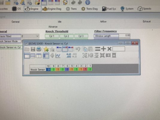
Now from me just switching these 2 cyls (#2 & #6) KS mic assignment to the opposite mic than the 1 they were originally assigned to.......that leveled out the cyl noise floor across all 8 cyls & still using the same OEM cyl knock sensitivity threshold map settings for all 8 cyls, I can now get to a total of 30* total WOT timing & still maintain a clean run w\o cyl knock............a full 12* additional spark advance timing at WOT..........just from switching #2 cyl & #6 cyl to use the opposite KS mics than the 1 they were originally assigned to, which corrected the distance discrepancy Ford intentionally induced into the cyl noise floor to artificially RAISE this to fully unload the engine so it would actually NEVER reach cyl knock BUT would also intentionally cut total engine output potential to a level that this engine.....if left uncorrected......could actually run for in excess of 300,000mi-500,000 mi if serviced timely & properly.

If this ain't intentionally neutering in a very covert way an engine's output capacity.......I don't know what is.

That 12* spark timing cut is easily worth in the range of approx 80 HP-100 HP all by itself..........not counting all the other items of miscues I've ran across\uncovered while tuning this 4.6L 3V thru this SO ECU during my early tuning "career".

I really can't fathom that this was not found & corrected before now.......what, 18 yr span this engine\ECU combination has been out......until I accidentally discovered it & made the correction to the OEM stock tuning to use the OEM stock tuning to its full capacity w\o butchering it up to pieces?

Then Ford really hid this very well by using Global Mode so the cyl knock would "look" legit thus no one would even think to question the KS mic to cyl assignment settings but would easily suspect the cyl sensitivity threshold map tuning..........thus no matter what you did to them, this OEM KS mic to cyl assignment setup always had them covered.

I hope my Coyote brethren are paying attention......................

Mind boggling, just mind boggling.....................

PS edit--Also, if you look at the Ford '09 OEM base BKT\MBT Spark Advance timing maps\BKT & MBT VCT Spark Multi Adder timing maps\ Airload\VCT load map & KS max spark advance timing map & remember that this SO ECU's OS is coded to look at the BKT side vs the MBT side & will use the LOWER of the 2 sides for all spark advance timing for engine AND that Torque Management always uses the MBT Spark side to calc engine TQ output......you should also by now pick up how Ford also set up the BKT side to essentially be a false mirage......the ECU will NEVER use any of the BKT spark advance timing or any of the BKT spark adder correction timing due to the fact that Ford set all this up so that the MBT spark timing side would ALWAYS BE THE LOWER OF THE 2 thus the ECU would never actually use the BKT spark timing or any of its spark adders......including the BKT VCT Spark Multi Adders or the KS spark advance adder timings--only the BKT Spark retard corrections--thus here was another way that Ford set this up to neuter this engine's HP\TQ capacity........but if you were to data log this.......the Spark Source would always show "Borderline" spark tables were being used due to the KS spark advance getting clipped by the base MBT Spark Advance timing\MBT VCT Spark Multi Adder timings so the ECU won't show that the spark source was actually "Base", which is what will show if the ECU determined that the MBT spark timing was the lower of the 2......thus hiding in plain sight once again........if any tuners weren't paying attention to this & kept messing w\ all this in its OEM configuration layout, then their tuning would've also been skewed as well.

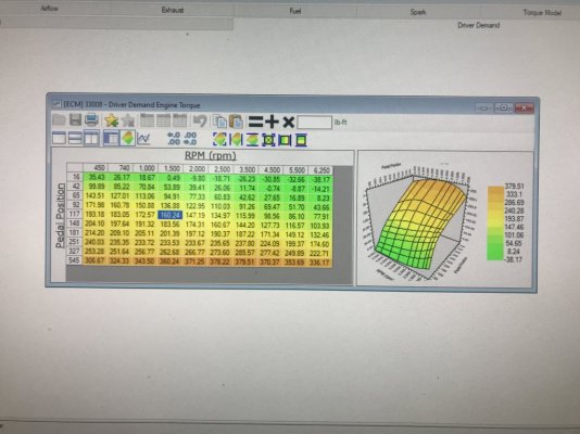
This is why I completely rearraigned all of this (the final mapping I posted in earlier post in this thread) according to the OS code line process mapping I figured out thru observing these OEM tune calibrations & many data logs to figure this out so that my BKT side wouldn't exceed the MBT side so ALL of the BKT spark side will get applied but also set up the MBT side to mirror the BKT VCT Spark Multi Adder correction timing into its TM calcs & maintain a 2 1\2* spread between them w\ the BKT side fully added--including all KS spark advance--to also allow any BKT IAT or ECT Spark Adder Correction from lower IAT\ECT temps to be added when called for w\o crossing the MBT spark threshold so all can be taken advantage of w\o being clipped & TM can fully optimize engine TQ output w\o any interference & properly match up to the BKT spark side that is actually being used to operate the engine..........once I finally recognized that the BAMA TM DD TQ Request map settings were fubar & had TM all jacked up so reloaded the Ford '09 OEM vers then tweaked it to fit my tastes w\o destroying the underlying X-Y axis scaling that matched up w\ the rest of the OEM stock TQ tuning still being used so TM would calc accurate engine TQ output & properly control the engine.

Thought I'd bring this to attention as well while I was at.

I'll keep saying it..............the 4.6L 3V engine's output was so neutered by Ford across its 6 yr production run it ain't funny........

Ford 09 OEM BKT MBT Spark Advance VCT Cam Profile for TQ Management.JPG

Ford 09 OEM KS Mic to Cyl Assignment Map.JPG

GlassTop09 Final KS Mic to Cyl Assignment Map Swapping #2 cyl #6 cyl Assignment.JPG
 
Last edited:

GlassTop09

Senior Member
Joined
May 24, 2019
Posts
1,145
Reaction score
526
Location
Farmington, NM
Just letting y'all know that, as of yesterday evening, I've just scored on an open box, NIB (the outer Ford Racing packaging box is missing but the cams are still in the NIB boxing they are individually boxed in & never been installed) set of FRPP Hot Rod cams off EBay for $750.00 + tax w\ free shipping from a speed shop's EBay listing in Van Nuys, CA that is getting rid of their inventory of 3V parts (display items), so in the future I'll be retiring these Lunati VooDoo #21270700 cams from service.
FYI.....................

Just got these FRPP Hot Rod cams delivered to my door this afternoon.........all came in the original Ford Performance outer\inner packaging & both camshaft's ID numbers checked out, so all is good. Seller really packaged these things very well, so they shipped unscathed.......right down to the outer box condition!

Gonna pick up a set of cam phaser bolts then at some time in the future, I'll be installing them & retiring my set of Lunati VooDoo #21270700 cams into storage along w\ my set of OEM stockers.

Looking forward to tuning these cams to see if my hunches learned from modeling these FRPP Hot Rod cam's Ford-given cam adv dur timing points vs the Ford-given OEM stock cams's adv dur timing points are true & the suspected HP\TQ curves actually show up thru this SO ECU w\ VCT..............
 

GlassTop09

Senior Member
Joined
May 24, 2019
Posts
1,145
Reaction score
526
Location
Farmington, NM
FYI....................

Just got back last night from being OOT on family business & I drove my Stang home & back........so approx 2,000+ mi over a 6,000'+ elevation drop\rise from essentially "desert" to "lush" landscape (oxygen limited to oxygen rich) & I've observed a few things concerning tuning these engines using the OEM SO ECU..............

1st, you need to take into account the topology of where you're doing the tuning to then make some allowances of any potential changes--whether mechanical or computer programming--that may be encountered that will affect how the ECU's TM will control the engine. So, I now better understand how engine "bucking" is created......yes, cam profile is an influencer, but the overarching thing is how the engine is set up to be used thru TM during\around engine idle speeds. Up here in the US 4 Corners area where there is very little "flat & level" geography, my tuning is reflecting this......up here, after making all the changes\repairs tuning-wise along w\ my 3.91 gear ratio\26" dia tires (setting a mean net ratio of 4.02:1) my engine doesn't hardly buck at all, even using the heavy 1st trans gear 3.38:1 ratio taking off & creeping around........but when I was down in the Longview, TX (essentially E. TX) area w\ my engine breathing in all that oxygen rich air & the topography being nowhere near as in the US 4 Corners area, using 1st gear was essentially a hot mess some of the time as the engine was so unloaded thru the mechanical gearing for the surrounding topography & at the same time was so "excessively TQ requested" thru the TM DD TQ Request 750 RPM column\16 A\D count row idle TQ of 26.14 ft-lbs using my Lunati VooDoo #21270700 cam timing profile so either way, during idle, the engine tended to want to buck around quite a bit in 1st gear from TM trying to constantly chase between this trying to control the engine once the clutch was engaged, I quickly realized that while down there, I needed to use 1st gear to only start the car to move then quickly shift into 2nd gear to put enough mechanical loading on engine so TM can now calm down & smoothly calc idle TQ output from the existing TM DD TQ Request to control the engine. This got real bad during my trip home going thru the DFW area during morning rush hour traffic.......raining on top of it as well......along w\ all the road work also going on.......so had to do a LOT of idle creeping from slow moving traffic.......until I started shifting into 2nd gear as soon as car started moving in 1st gear as I had plenty of idle TQ requested for TM to use to maintain the engine idle speed of 740 RPM's w\o having to fluctuate the TB hardly at all (where the bucking is coming from) thus maintain good tight airmass flow control into engine so ECU is mainly using secondary idle spark alone to control engine idle speeds then ride 2nd gear as long as I could before being forced to downshift into 1st gear to stay away from the bucking.

It ain't so much the cams themselves--even though their cam timing profile can influence this...........it's how well all the front-end tuning is setup\matched to the mechanical components under ECU TM to operate under the associated environments expected to encounter while under the ECU's adaptive idle speed control algorithm........IOW's a balance has to be maintained.

Good part is that all of this is an easy fix w\o having to change anything mechanically...........once you understand how\why it's happening. So, another item is also true w\ this engine\ECU combo.......there is no such thing as low end TQ loss under the curve w\ any camshafts used in this setup......IF you actually reconfigure VCT & TM to "fit" the camshaft's cam timing profile to gain the necessary TQ leveraging.

Heck in my case.......under certain conditions.......I've clearly overdid this & my engine is producing too much idle\low speed TQ off TM operations......w\ a set of aftermarket non-OEM cams.........using CMDPs!

IMHO, the TQ losses are seen simply due to tuners trying to keep using the same OEM VCT cam timing\TM OEM 16 A\D count row\740 RPM column idle TQ request along w\ the same fuel inj EOIT CA ref setting Ford set up to use w\ the OEM stock cams timing profile......w\ a different cam timing profile. I have 2 examples in hand of a couple of tuner's tune calibration files--besides my prior tuner--that I got off HPTuners BBS Ford tuning forums that show this in spades using these very same FRPP Hot Rod cams......both tuners also were looking for help at the time as the expected HP\TQ outputs they were getting from these Hot Rod cams were not meeting their expectations........

You can learn from other's mistakes..........if you just learn to look, listen then do the legwork to either verify or disprove what is stated & not just take at face value what other folks say........regardless of how long they've been doing it or how "experienced" they say they are.

This goes for myself included..........

So, going forward, I'll definitely be adding into my tuning routines to find some flat areas to use to "tune" for this as well to try to cover both ends so car will be manageable regardless of where I'm driving it as I KNOW these FRPP Hot Rod cams timing profile is gonna be needing this type of attention to help them operate well under TM in both steep & shallow topographies.

Also, this trip has now worked the ECU enough to get a true sense of how all is stacking up for both MPG & emissions.........the results are again very stellar. Going down, my MPG started at 19.1 MPG but halfway thru the trip (roughly 500 mi & 5,000' elevations drop after the 1st fill up w\ E10 93 oct fuel in Amarillo, TX.... used this fuel the rest of the way) hit 22.6 MPG & settled down here the rest of the way in. Checked the Cat CE Ratio at the hotel in Longview, TX as follows...B1 @ .117, B2 @ .121....started on trip at B1 @ .141, B2 @ .156 off last check so emissions got better in more dense warmer air, not worse......speaks highly of engine's operating efficiency thru the tuning. On the way back home, she started out on E10 93 oct fuel at 22.4 MPG, quickly moving back to 22.6 MPG within 50 mi then settled in here.....until I filled up in Claude, TX at a Valero station that had E10 91 oct fuel (which from here on out was the fuel used....again approx halfway), after this the MPG started to slowly climb from 22.6 MPG to 23.3 MPG when I backed into my driveway last night (this was purely due to engine coming back under the conditions it was originally tuned under.....mostly increasing elevation & lowering IAT......specifically what MAF Adaption is actually making fueling corrections from airmass density corrections--if left enabled in tune calibration--using the MAF sensor density\IAT readouts to correct the hard coded LWFM airmass map calcs under Ford's vers of SD......just as it did when going down in elevation along w\ warming IAT) thus the modeling is spot on accurate. Checked the Cat CE Ratio readouts today as follows......B1 @ .102, B2 @ .094......so emissions got even better on the return trip home......all this is coming thru them Motive Gear 3.91 gears running 26.1" dia Conti Extreme Contact DWS06 tires at a mean effective ratio of 4.02:1 ..........w\ a 4.6L SBE NA 3V engine in good operating condition w\ 170,693 mi now on the clock.

But I did have 1 snafu...........found my rt front marker light\turn signal yellow housing's inner mount tab had come out of its bumper mounting hook & was flopping off the rear mounts & wiring harnesses.........nothing hit the front of the car at all during the entirety of the trip. Checked the bumper & found that the bumper hoop that the marker housing's mounting tab went into had broken off on 1 side........so NOW I need a new front bumper......but I'm gonna give it a good shot at fixing it by using some JB Weld to see if this will hold it or not before going there, since checking on CJ Pony Parts site a new GT std front bumper cover unpainted is running for $641.95 + tax.

The money isn't the issue.........the issue is this current front bumper isn't Ford OEM part & is most likely the reason why I'm in the situation I'm in now (PO used an aftermarket non-Ford OEM front bumper cover for repairs to an accident(s) that wasn't reported to insurance......VIN came back clean when I ran it prior purchase back in 10-2017 but when doing other work on car after purchase, the evidence I ran into said otherwise).

Genuine Ford OEM body components for these 05-09 S197s are getting harder & harder to find\locate.......as I'm positive that if this part was a genuine Ford OEM part, I wouldn't be talking\complaining bout this right now...........

Otherwise, all was fantastic w\ the Stang!
She put the "C" in cruiser & all the Dynamat\Dynaliner sound deadener installed showed its weight in gold!

Gonna be a little hard for me to pull these Lunati's out............but the FRPP Hot Rod chop has spoken & I can't resist it anymore!

PS--Damn 3V's & their firing order..............................
:beer:
 
Last edited:

GlassTop09

Senior Member
Joined
May 24, 2019
Posts
1,145
Reaction score
526
Location
Farmington, NM
But I did have 1 snafu...........found my rt front marker light\turn signal yellow housing's inner mount tab had come out of its bumper mounting hook & was flopping off the rear mounts & wiring harnesses.........nothing hit the front of the car at all during the entirety of the trip. Checked the bumper & found that the bumper hoop that the marker housing's mounting tab went into had broken off on 1 side........so NOW I need a new front bumper......but I'm gonna give it a good shot at fixing it by using some JB Weld to see if this will hold it or not before going there, since checking on CJ Pony Parts site a new GT std front bumper cover unpainted is running for $641.95 + tax.

The money isn't the issue.........the issue is this current front bumper isn't Ford OEM part & is most likely the reason why I'm in the situation I'm in now (PO used an aftermarket non-Ford OEM front bumper cover for repairs to an accident(s) that wasn't reported to insurance......VIN came back clean when I ran it prior purchase back in 10-2017 but when doing other work on car after purchase, the evidence I ran into said otherwise).

Genuine Ford OEM body components for these 05-09 S197s are getting harder & harder to find\locate.......as I'm positive that if this part was a genuine Ford OEM part, I wouldn't be talking\complaining bout this right now...........
FYI..........

This is now repaired............good ole JB Weld to the rescue!
 

GlassTop09

Senior Member
Joined
May 24, 2019
Posts
1,145
Reaction score
526
Location
Farmington, NM
1st, you need to take into account the topology of where you're doing the tuning to then make some allowances of any potential changes--whether mechanical or computer programming--that may be encountered that will affect how the ECU's TM will control the engine. So, I now better understand how engine "bucking" is created......yes, cam profile is an influencer, but the overarching thing is how the engine is set up to be used thru TM during\around engine idle speeds. Up here in the US 4 Corners area where there is very little "flat & level" geography, my tuning is reflecting this......up here, after making all the changes\repairs tuning-wise along w\ my 3.91 gear ratio\26" dia tires (setting a mean net ratio of 4.02:1) my engine doesn't hardly buck at all, even using the heavy 1st trans gear 3.38:1 ratio taking off & creeping around........but when I was down in the Longview, TX (essentially E. TX) area w\ my engine breathing in all that oxygen rich air & the topography being nowhere near as in the US 4 Corners area, using 1st gear was essentially a hot mess some of the time as the engine was so unloaded thru the mechanical gearing for the surrounding topography & at the same time was so "excessively TQ requested" thru the TM DD TQ Request 750 RPM column\16 A\D count row idle TQ of 26.14 ft-lbs using my Lunati VooDoo #21270700 cam timing profile so either way, during idle, the engine tended to want to buck around quite a bit in 1st gear from TM trying to constantly chase between this trying to control the engine once the clutch was engaged, I quickly realized that while down there, I needed to use 1st gear to only start the car to move then quickly shift into 2nd gear to put enough mechanical loading on engine so TM can now calm down & smoothly calc idle TQ output from the existing TM DD TQ Request to control the engine. This got real bad during my trip home going thru the DFW area during morning rush hour traffic.......raining on top of it as well......along w\ all the road work also going on.......so had to do a LOT of idle creeping from slow moving traffic.......until I started shifting into 2nd gear as soon as car started moving in 1st gear as I had plenty of idle TQ requested for TM to use to maintain the engine idle speed of 740 RPM's w\o having to fluctuate the TB hardly at all (where the bucking is coming from) thus maintain good tight airmass flow control into engine so ECU is mainly using secondary idle spark alone to control engine idle speeds then ride 2nd gear as long as I could before being forced to downshift into 1st gear to stay away from the bucking.
FYI......................

As of today, this is now fixed in my tune calibration..............the issue was being caused by the settings in 3 of the 2D maps under Idle\Airflow\Dashpot Airflow idle control being out of "synch". The base Idle Dashpot Min 2D map sets the min airflow the dashpot idle control is to use when vehicle is moving under desired idle speeds (the idle RPM's you set for P\N & Drive) & these settings were set good between the Y-axis 650-1,400 RPMs scaling so around the 740 RPMs area the dashpot idle min airflow used was in close agreement w\ the actual idle MAF lbs\min readout of .77 lbs\min when in P\N & Drive (manual trans uses the same desired speed setting of 740 RPMs in both of these positions.......autos usually have 1 set desired idle speed for P\N then a different set idle speed for Drive).

The issue was a clash between this 2D map settings & the other 2 Idle Dashpot Min 2D map's settings.....the Idle Dashpot Min (4th gear, no decel) 2D map & the Idle Dashpot Min (4th gear) 2D map. All 3 of these 2D maps use the exact same Y-axis scaling so the ECU is polling all 3 of these at the same time during idle, so whenever the ECU needs to switch from adaptive idle control to the dashpot idle control (like when you put vehicle in gear if manual--or drive if auto--and start vehicle to move under idle TQ w\ foot off the APP) it polls these 3 Idle Dashpot Min 2D maps to get direction on setting the min airflow lbs\min to use as coarse idle speed control to then follow up w\ fine spark timing control to maintain the TQ needed to hold the desired set idle speeds under a load from being in gear. Now even though 2 of these isn't supposed to be used until the trans gear selector indicates to the ECU that the trans is in 4th gear, the ECU was in fact looking at all 3 of these anyway......the 2 Idle Dashpot Min 4th gear 2D maps had lower min lbs\min coarse airflow settings in the same 650-1400 RPMs Y-axis scale (650 row in both was set at .25 lbs\min & the 1,400 RPM row in both was set at .68 lbs\min) than the 1 mentioned above (650 row was set at .33 lbs\min & 1,400 RPM row was set at .85 lbs\min) so the ECU was getting confused as to which set of settings to use thus it kept oscillating the TB back & forth between all 3 of these trying to maintain the desired set idle speeds while under load w\ vehicle moving........even though 2 of them wasn't supposed to be used yet (trans was being used in 1st thru 3rd gears most of the time when extended idle creeping in heavy morning rush hour traffic in DFW area last Thursday) so it appears that HPTuners may have erred on the operational descriptions given of the functions of these 2 Idle Dashpot Min 4th gear 2D maps to not inform that the ECU actually is actively polling all 3 of these Idle Dashpot Min in-gear idle speed control 2D maps whenever the vehicle is put in gear under ECU idle speed control........because they are all identically scaled 2D maps & provide the exact same type idle speed control for the exact same purposes........

Anyway................so I used the HPTuners Editor's vert Smoothing & reset both the Idle Dashpot Min (4th gear, no decel) & Idle Dashpot Min (4th gear) 2D maps Y-axis scale settings to essentially be the same as the base Idle Dashpot Min 2D map's Y-axis scale settings so the ECU won't be getting confused anymore & also smoothed the Idle Dashpot Decay 2D map's Y-axis scaled settings as well while I was in there, saved & flashed in the ECU & voila!........no more idle creep TB oscillations anymore..........she now comes up & steadies out on desired idle speeds @ 740-750 RPMs w\o any TB oscillating at all regardless of which gear I used to creep around in.......even on some road inclines & declines as well as flat & level roads........

Also......this had nothing to do w\ the Lunati VooDoo cam profile being used & wasn't an influencer in this issue at all.........issue was in the tune calibration settings\OS programming.

Well.........I've now bagged yet another squirrel in this tune calibration that I thought I had them all bagged.............maybe this 1 is the last......?????????

This has already been corrected in the upcoming FRPP Hot Rod cams tune calibration file.

Posted for informational purposes.
 
Last edited:

RRPD4130

Junior Member
Joined
Sep 7, 2021
Posts
10
Reaction score
1
Location
The Last Citadel of Freedom-Great State of Texas
Best book I read this month. Fellow retiree, precisely the same motivations here, but just a Padawan to your Jedi Master. Still using my 2007 BamaSF3 (rebranded later years) with the original e-mail Bama 93 & 93Nitrous tunes, which are excellent for the era, but I am retaking control of my tech across all paradigms.
Thank you very much for sharing your efforts.
Godspeed, sir.
 

GlassTop09

Senior Member
Joined
May 24, 2019
Posts
1,145
Reaction score
526
Location
Farmington, NM
FYI.............................

To bookend into an ending to this thread..................

Provided below are the final setups\settings of consequence using these Lunati VooDoo #21270700 cams based off the 10* ATDC Power Stroke Crank Positioning criteria that Ford used to model their cams (the OEM stock cams as well as the FRPP Hot Rod cams) to achieve the results they were looking for.........

These Lunati Power cams have been stellar performers for what they were purposed to do. I bought these after going thru a lot of research on these due to hardly anybody (at least in this BBS) running these cams so I took it upon myself to try them out.

These are very similar in cam timing profile design to the Comp Cams XFI Stage 2 #127200 cams so should match up very closely to each other in HP\TQ output performance across the board.

They have served me very well over the last 4 1\2 yrs.......only recently have I gotten the opportunity to experience their full & true available HP\TQ output capabilities when the tuning is set up to allow this Spanish Oaks ECU's Torque Management to fully & accurately operate using all the tools in the tune calibration\OS programming that the Ford engineers provided to optimally manage this engine using it's VCT DEPS system along w\ it's Spark Advance BKT\MBT timing system thru the Ford patented\designed version of Speed Density\VE Engine Control system using the MAF sensor as primary airmass density\IAT correction to SD airmass calcs monitored thru the IPC Wheel TQ Error checking system which is part of TM operations...................the drivability & responsiveness of the car improved by a factor of 15 across the board due to the positively measured increase of off idle\low RPM thru part throttle mid-range TQ output application\response under CL operations........that only by using TM to its fullest can be achieved.

WOT OL\PE HP\TQ output is showing to be very close to the same vs what my prior tuner achieved (right at the same ft-lbs EBTQ output at same engine RPM in 3rd gear @ 4734 RPMs.......prior tuner: .75 air load, 22.56 lbs\min MAF, 27* max spark timing, VCT @ 0* cam retard timing (KS were found disabled along w\ VCT during WOT only in prior tuner's tune) @ 217 ft-lbs EBTQ. GlassTop09: .74 air load, 21.47 lbs\min MAF, 19* max spark timing, VCT @ 11* cam retard timing (all verified fully active & working) @ 217 ft-lbs EBTQ.........) so final WOT OL\PE HP\TQ output off my tuning should hopefully very closely repeat the 352HP\320TQ peaks as measured on 7-28-21 dyno sheet on pg 8, post #143 in this thread by these results shown thru HPTuners VCM Scanner datalog data.........

IM Readiness Mode 6 emissions performance is stellar for a 4.6L 3V SBE V8 w\ 171,685 & counting mi using non-EPA cert engine components along w\ a non-OEM custom tune calibration. Proper & accurate up-front tuning preparation\setup application across the board is key to achieving\maintaining these results.

So, a good overall result coming out of these Lunati VooDoo #21270700 cams indeed.

It's gonna be a hard thing for me to pull these cams out & retire them after experiencing them when all is fully tuned out & operating at its fullest potential, but its time to move to the final chapter & install a set of FRPP Hot Rod cams along w\ a full timing refresh\upgrade for the long haul.

Enjoyed every minute of the journey!

:beer:

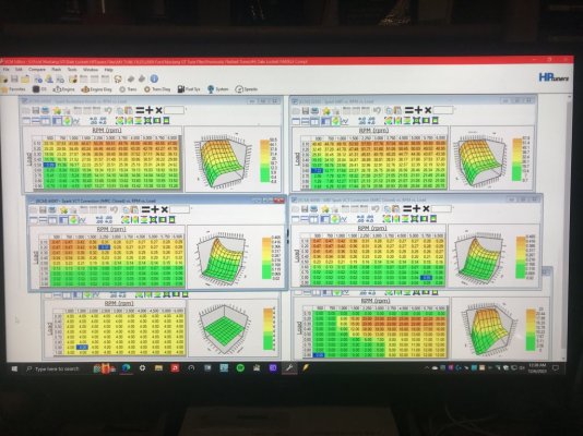
GlassTop09 Final BKT MBT Spark Advance VCT Cam Profile for Torque Management.JPG

GlassTop09 Final Ford Racing 62mm TB PTA EA Mapping for ETC SD Throttle Control.JPG

GlassTop09 Final KS Mic to Cyl Assignment Map Swapping #2 cyl #6 cyl Assignment.JPG

GlassTop09 Final TM DD TQ Request Map for TQ Management.JPG

Comp Cams XFI NSR Stage 2 #127200.PNG

Lunati Voodoo #21270700.PNG
 

GlassTop09

Senior Member
Joined
May 24, 2019
Posts
1,145
Reaction score
526
Location
Farmington, NM
WOT OL\PE HP\TQ output is showing to be very close to the same vs what my prior tuner achieved (right at the same ft-lbs EBTQ output at same engine RPM in 3rd gear @ 4734 RPMs.......prior tuner: .75 air load, 22.56 lbs\min MAF, 27* max spark timing, VCT @ 0* cam retard timing (KS were found disabled along w\ VCT during WOT only in prior tuner's tune) @ 217 ft-lbs EBTQ. GlassTop09: .74 air load, 21.47 lbs\min MAF, 19* max spark timing, VCT @ 11* cam retard timing (all verified fully active & working) @ 217 ft-lbs EBTQ.........) so final WOT OL\PE HP\TQ output off my tuning should hopefully very closely repeat the 352HP\320TQ peaks as measured on 7-28-21 dyno sheet on pg 8, post #143 in this thread by these results shown thru HPTuners VCM Scanner datalog data.........
There is a specific subject I overlooked when I made this statement.............when I got the dyno'd 352 HP\320 TQ peaks, the car was equipped w\ 3.73 gears on an OEM Ford Trac-Lok LSD diff & Kooks Race Cats installed in Kooks LTH exhaust midpipe.........the EBTQ output numbers noted in my tuning are obtained w\ 3.91 gears on an Eaton Tru-Trac LSD diff & MF #5461336 CARB-cert EO# D-193-140 TWC OEM grade aftermarket cats installed in same Kooks LTH exhaust midpipe......the only 3 items that were different component-wise.......all else is the same.

So, this may have an effect on the outcome..........by most accounts I've read off the 'Net, the TQ may go up slightly due to angular acceleration improvements thru loaded roller readout but the HP may go down slightly due to slower roller speeds at same engine RPMs.....but also may not affect the outcome much at all due to the rear gear ratios being so close to each other (only talking .18T difference between 3.73 to 3.91).

Really doesn't matter to me in the end............just making note of these component differences in relation to the 2 sets of measured WOT numbers.

FYI..............................
 

JC SSP

Senior Member
Joined
Nov 8, 2022
Posts
1,079
Reaction score
466
Location
FL
Minor changes that will yield minuscule power loss or gains. The ambient weather/temp would be more of a determining factor…

Your still at 400HP at the engine. That’s good power!
 

GlassTop09

Senior Member
Joined
May 24, 2019
Posts
1,145
Reaction score
526
Location
Farmington, NM
Minor changes that will yield minuscule power loss or gains. The ambient weather/temp would be more of a determining factor…

Your still at 400HP at the engine. That’s good power!
Yes sir..........especially from a set of cams that no one seems to want to run...........

Lunati Power was & still is a big name in the performance world.........especially in SBC\BBC, SBF\BBF engines & has been around for about as long as most of the other big well-known names like Crane, Isky & Crower.

The company went thru a restructuring during the late 1990's-early 2000's thus they were slow (just like Crane, Crower & Isky as well) to move into the Ford 3V Mod Motor market due to the advent of VCT design\usage thus left this market wide open for Comp Cams to essentially take the lion share of marketing by being the lone cam manuf to fully embrace this "new" Ford platform & fully develop cams from the start that work very well w\ this engine\ECU combo to provide us enthusiasts a full range of choices to essentially cover any level of power & fully take advantage of the VCT design\use..............just like Brian Tooley @ BTR is doing now w\ the GM Gen V & up LS\LT series engines that GM provided w\ their version of VVT (they use this acronym instead of VCT to not step on Ford naming copyrights.....even though this is the same type of control--a DEPS system--they also use the actual cam degree timing to set their VVT which can be more confusing for tuners due to the fact to equate the cam-to-crank relationship, a tuner will need to multiply the cam degree timing X 2 in their head.......whereas by Ford using the actual crank degree timing to determine the same cam degree timing, this is easier to apply & is simpler to use to manage any piston to valve clearance issues when moving cams around using VCT by equating the cam seat-to-seat open\close timing to the actual piston top position in bore thru using the crank degree timing for cam degree timing.........but both generally work exactly the same way & in the same manner) & is doing the exact same things now w\ his VVT camshaft designs--except Brian still uses .050" lift dur specs in which you have to add 12*-15* to in order to correct back to seat-to-seat timing--that Ford tried to do years ago w\ these Hot Rod cams by providing all the .006" adv dur seat-to-seat cam timing profiles\optimized WOT cam timing profiles to help tuners to tune these to optimal performance outcomes across the board.

And we're seeing the GM side initially do the exact same things the Ford side did w\ this 3V............but it appears that Brian Tooley @ BTR is starting to break thru to the GM tuners to start embracing VVT, stop defeating it & use it to its fullest potential by essentially doing all the VVT "tuning" for them on all of his VVT cam designs & providing it on his web site for folks to acquire & apply it "plug & play" style.
 
Last edited:

GlassTop09

Senior Member
Joined
May 24, 2019
Posts
1,145
Reaction score
526
Location
Farmington, NM
https://www.s197forum.com/threads/frpp-hot-rod-cams.142371/page-2 post #36

A dyno sheet or datalog pics just can't capture everything that is coming out of all this work..........
To convey................................
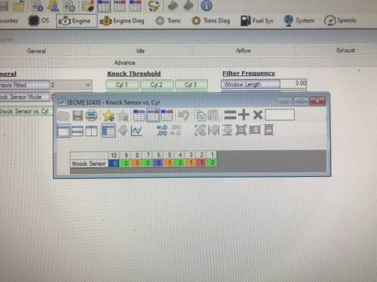
If you look at the #89 Datalog 17* ATDC Power Stroke TQ Leveraging Steep Hill Climb pic vs the #109 Datalog 10* ATDC Power Stroke TQ Leveraging Steep Hill Climb pic you'll note in the #89 Datalog pic there are 2 blips in the tracking........these 2 blips are from me having to 1st downshift from 5th gear OD back into 4th gear to regain speed due to engine TQ output falling off thru TM maxing out then upshift back into 5th gear OD after regaining momentum so regained engine TQ can complete the hill climb.............that you don't see occurring in the #109 Datalog pic due to the engine TQ output not falling off at all due to TM having the extra TQ available thru just advancing the VCT cam timing across the board by 7* in the Airload VCT cam retard timing map then reset (cut IOW's) spark timing to match back up fully w\o knock.......in fact, the dip you see in this pic is due to me having to let up on the APP due to TM having the car ACCELERATING & gaining speed up this same steep hill in 5th gear OD using DBW to readjust to changing engine loads w\o any extra APP input from me & closing in on another driver going slower than I was until I could check my side mirror for lane clear to then move into the passing lane then speed back & pass the other vehicle using the APP only while car was still in 5th gear OD moving up this same steep hill w\o any downshifting at all..........

Car seems to just drive itself at times................

The feeling that this kind\type of at the ready, available engine HP\TQ output gives to the driver is what just can't be conveyed thru any dyno sheet or datalogs........also demonstrates the full power\ability of TM when it is set up properly & all supporting maps\settings are set up optimally for TM to generate max engine TQ output............just can't be expressed into words..........has to be experienced\felt in order to appreciate it.

FYI............................
 

Support us!

Support Us - Become A Supporting Member Today!

Click Here For Details

Sponsor Links

Banner image
Back
Top