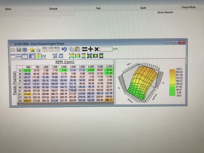
Lunati VooDoo #21270700 Camshafts

GlassTop09

Senior Member
Joined
May 24, 2019
Posts
1,141
Reaction score
525
Location
Farmington, NM
When the 2 maps are overlaid like these are (I can see a piece of the bottom map in the upper left corner) I can see how difficult it can be to distinguish between them w\o a good map legend to go off of.
 

GlassTop09

Senior Member
Joined
May 24, 2019
Posts
1,141
Reaction score
525
Location
Farmington, NM
FYI.............................

Just read recently in local paper that San Juan Co (in 4 Corners area of NM) has failed the low ozone concentration limit (this is 1 threshold for whether to consider instituting passenger vehicle <8,500 lbs GVWR emissions certification testing for registration........have had only DOT emissions certification up here in the past for heavy industry.....ie, diesels >10,000 lbs GVWR) so this IMHO is gonna start the ball rolling.................in 3-5 yrs I predict this will become a reality up here.

So as long as the State uses the same passenger vehicle emissions certification criteria it is currently using for Bernalillo Co (Alburquerque metro-plex), I should be in good shape as I'm currently configured w\ my Stang.

Had a gut feeling that this was headed our way sooner or later.........(reference pg 8, posts #146, #147 in this thread) since NM is committed to go green (doing away w\ all coal generated electricity in the State.....switching to solar & wind w\ natural gas-powered electric generation as backstop).

On this note, I also saw a Ford F-150 Lightening EV pickup along w\ a red Tesla Plaid EV today while driving on I-25 N between Alburquerque & Bernalillo (headed home from visiting SIL in Alburquerque & attending a concert at Isleta Casino for wife's birthday present over the weekend) in my '03 Dodge Ram 1500 pickup so the trend goes on...............
 

GriffX

Member
Joined
Sep 28, 2017
Posts
518
Reaction score
175
Hi, I can get an used Ford Racing Hotrod cam, but I'm not sure because I drive a lot in city traffic.
And I have to pass emission inspection (they check CO level on 2000 rpm and lambda value of the monitor sensor)
My other mods are FR CAI, charge motion delete plates and 3.37 diff with Eaton trutrac.
What do you think about this cam?
Thanks!
 

GlassTop09

Senior Member
Joined
May 24, 2019
Posts
1,141
Reaction score
525
Location
Farmington, NM
Hi, I can get an used Ford Racing Hotrod cam, but I'm not sure because I drive a lot in city traffic.
And I have to pass emission inspection (they check CO level on 2000 rpm and lambda value of the monitor sensor)
My other mods are FR CAI, charge motion delete plates and 3.37 diff with Eaton trutrac.
What do you think about this cam?
Thanks!
Hi GriffX,

Well, I'll give you my reasoning along w\ a couple of pictures as follows:
Ford OEM Production 4.6L Cams.PNG FRPP HotRod Cams.PNG
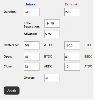
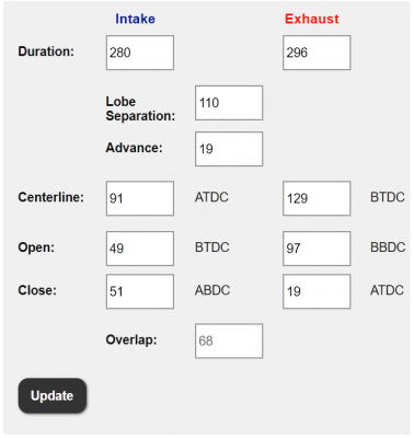
On the left is the advertised duration (at .006" lift) numbers for the OEM Ford stock 4.6L camshafts & on the right are the same advertised duration (at .006" lift) numbers for the FRPP Hot Rod camshafts. I use these numbers to follow Ford's usage for VCT calibration\setup as provided in the Ford HotRod Cams installation guide (used FRPP numbers ran thru Summit's Cam Timing Calculator to get the LSA, GI advance, OL & Int\Exh Centerlines for both camshafts). These numbers represent the camshafts at 0* VCT cam timing (or "straight up" as is called) thus in the tune will be at idle......this is important to know to understand what I'm going to say to answer your posting.

Since you do a lot of city driving & you have 3.31 gears, these Hot Rod cams are not gonna be a smooth operation in start\stop manual trans operations due to the power side cam timing (IVC thru EVO), mostly due to the EVO being at 97* BBDC (exhaust valve opens during power stroke before crank throw reaches its full 90* throw position, ie full stroke length or max leverage) thus is bleeding off cyl pressure before crank throw is at full leverage point while the following cylinder is still in compression\firing position but NOT in power stroke position to start applying its force to crankshaft yet (roughly 17* ATDC) thus the TQ will momentarily drop off until the built up flywheel momentum (inertia) energy finishes crank rotation while also pushing the vehicle forward to bring the following cyl into position in the power stroke to then begin to apply it's force to the crank throw thus the TQ will then be reapplied to crank & flywheel momentum regained......thus the "rocking" or "bucking" these cams assert during low RPM operation until the engine RPM's reach a point where the flywheel (or TC for autos) momentum (inertia) can effectively "cancel" this out (why most raise the engine idle speed to compensate for). This dynamic is THE MAIN REASON why these cams lose low speed TQ relative to OEM cams (OEM cams EVO is at 80* BBDC.....which is a full 10* AFTER the crank throw has rotated thru its full length (90*) thus max leverage before opening the exhaust valve bleeding it's force off piston while at the same time the following cyl is at near optimum position at start of power stroke to immediately begin applying its force from compression\firing practically without hardly any needed flywheel momentum so hardly any TQ loss occurs during this "handoff" from leading cyl to following cyl during the power stroke cycle thus all force....including the flywheel's inertial momentum.....is being used to drive vehicle forward). Most say this is due to large OL, but the OL occurs during the induction side of cam timing (IVO thru EVC) or exhaust\intake, not the power side of cam timing, thus OL only affects the engine's ability to BREATHE or cyl filling if you prefer thus has absolutely nothing to do w\ the power application outside of fuel atomization\swirl....which the fuel inj EOIT ref CA timing has a LOT to do w\ port EFI fuel atomization\swirl while the OL helps w\ cyl filling by taking full advantage of the exhaust scavenging while both Int\Exh valves are open to help draw in more air\fuel during transition from exhaust stroke into intake stroke.

This is why switching to shorter gears is needed\desired (IMHO, 3.73 min & up, depending on tire dia also being used if NA config) to provide the necessary mechanical TQ at low engine RPM's to offset the engine TQ loss at same w\ these Hot Rod cams to "balance this out" as well so car will be somewhat tolerable when driven at low engine RPM's (autos will have an advantage here due to TC coupling\multiplication vs a manual) relative to the stock cams. Now you WILL gain mid-range\top end HP\TQ vs the OEM stock cams due to the GI induction cam timing along w\ VCT retarding the cam timing even further to fully optimize the engine BREATHING\cyl filling at high RPM's as long as the spark timing is properly set up to create enough dynamic compression to offset the static compression loss from VCT retarding the cam IVC timing.

If you can live with these low-speed engine characteristics of the Ford Hot Rod cams in tandem w\ your 3.31 gears then go for it........if not then IMHO pass them by. The rest will be up to how well the prospective tuner is familiar tuning while also maintaining the emissions (your referring to what is called in US the ASM 5-gas emissions cert test.....car is run under a load on a dyno in 2nd-3rd gear at 1,500 RPM's then at 2,500 RPM's while exhaust is sniffed to measure the NMOG, CO & NOx output to see if levels are below the set thresholds for MY of vehicle......in NM this test is an option to the OBDII PCM ran monitoring catalyst cert testing). This can be done but tuner will have to set the fuel stoich AFR accurately in tune to match the fuel being used so the PCM's EQ Ratio Lambda calc's are accurate along w\ the fuel inj CA reference setting set to match the Hot Rod cams adv dur cam IVO timing point so optimum fuel atomization\swirl is achieved (which will not be the same as stock cams.....HR cams are 49* BTDC @ 311* CA, OEM cams are 15* BTDC @ 345* CA) so combustion burns fully & most importantly CLEAN......which will also ensure max low speed TQ output w\ whatever physical cam timing being used & give you the best chance of passing this load cert sniff test.

Hope this helps.
 

GriffX

Member
Joined
Sep 28, 2017
Posts
518
Reaction score
175
Oh boy, I made a typo, I have 3,73 gears installed.

Thanks a lot. So, the minimum requirement you see is the 3,73 gear, which I have. The US sniff test seems to be more demanding than the German, because they only look if the CO drops below a threshold which is higher than the ULEV. The required CO level in the EU back in 2005 was a lot higher than the US. It was EURO4, the ULEV2 can be compared to EURO6. So emission looks good.

The last hurdle is the bank account ;)
Thanks for your time!
 

GlassTop09

Senior Member
Joined
May 24, 2019
Posts
1,141
Reaction score
525
Location
Farmington, NM
Oh boy, I made a typo, I have 3,73 gears installed.

Thanks a lot. So, the minimum requirement you see is the 3,73 gear, which I have. The US sniff test seems to be more demanding than the German, because they only look if the CO drops below a threshold which is higher than the ULEV. The required CO level in the EU back in 2005 was a lot higher than the US. It was EURO4, the ULEV2 can be compared to EURO6. So emission looks good.

The last hurdle is the bank account ;)
Thanks for your time!
Ah OK, my bad as I made assumption from your typing (and you have a 05 GT but didn't know the OEM trim package so assumed a Base instead of a Premium) that you still had OEM 3.31 gears......

IMHO a 3.73 axle gear is a minimum (w\ a 26" dia tire preferred but a 27" dia tire max......any tire dia size in excess of 27" IMHO need to move up to a 3.91 or 4.10 gear) when running HR cams (or any drop-in "lopey" cams for that matter) w\ a TR3650 trans in NA engine config (ran a LOT of final drive ratio pattern set checks using axle gear ratios from 3.55 thru 4.10 w\ TR3650 trans gear ratios along w\ tire dia sizes from 25" thru 30" vs engine RPM's at various MPH so not guessing here.....I put in the legwork) to provide enough mechanical TQ offset to help preserve clutch longevity\reduce hot spotting from excessive intentional clutch slipping\raising engine RPM's off idle to keep engine running until vehicle starts moving due to the lower low speed engine TQ output until the VCT can start retarding the cam timing to rectify the power side TQ loss (in OEM stock tune this is mapped in VCT load map to start becoming active > 1,000 RPM's unless initial engine load is =>30%......to match up to\work with the OEM stock cam timing profile.......from what I've seen in other's tune files most leave this area of the VCT load mapping set as OEM.....which ain't gonna help a lopey cam profile at all......VCT cam timing tuning can rectify this to a point w\ lopey cams to make it better coming off idle but still chop good at idle). Even OEM cam's low speed TQ output can benefit even more from finer VCT cam timing tuning in this area thus isn't something special......Ford just left a little on the table here to take advantage of.......once it's fully understood then applied.

IMHO, where most manual clutches take the most abuse\wear is during low speed, low RPM start\stop operations.....thus is also where good low speed, low RPM engine TQ output (along w\ the proper mechanical TQ gearing choices as well to match up) is a premium in overall clutch longevity\performance due to much less clutch slip modulation (thus less heat buildup & clutch wear so clutch grip\bite is maintained....if running std organic clutch discs) is needed to keep engine running at off idle RPM's <1,000 to start vehicle moving.

My 2 cents...............YMMV.

Hope all works out for you!

:beer:
 

GriffX

Member
Joined
Sep 28, 2017
Posts
518
Reaction score
175
Clutch is a good point. I had several tune iterations, because of erratic TB behavior from the CAI/CMDP tune when the car starts moving. And it cost me some clutch life. I have the 27" stock wheels.
I guess the marks from the roller followers are normal: upload_2023-5-23_21-0-14.png
 

GlassTop09

Senior Member
Joined
May 24, 2019
Posts
1,141
Reaction score
525
Location
Farmington, NM
Clutch is a good point. I had several tune iterations, because of erratic TB behavior from the CAI/CMDP tune when the car starts moving. And it cost me some clutch life. I have the 27" stock wheels.
I guess the marks from the roller followers are normal: View attachment 87413
The method I've used to determine that is the fingernail test......if I run my fingernail across the used cam lobes\cam journals surface & it doesn't catch, it's good.

Those markings, judging from the picture you sent, look normal to me visually on a used set of cams that has been run for a while.......

Hope this helps.
 

GriffX

Member
Joined
Sep 28, 2017
Posts
518
Reaction score
175
Should have run only 500 Mi, looks more to me, especially at the bearing (?) part and the
marks at the tip of the lobes.
Was probably used in the first place and removed again after 500 Mi.
 

GlassTop09

Senior Member
Joined
May 24, 2019
Posts
1,141
Reaction score
525
Location
Farmington, NM
MPG is the only item left to see where it ends up......but from initial observations it should top out within 20 to 22 MPG range when it is all fully learned\lined out PCM-wise after a few hundred miles of driving..
Typing this from my IPhone thru a hotspot (Internet service has been down for approx 10 days…….CenturyLink strikes again…..have work ticket submitted for repairs) to follow up on car progress after finish of self tuning. Have put in 800+ mi since (across 12 full drive cycles) & car is performing very well & currently PCM has adjusted MPG up to 21.3………to date PCM hasn’t plateaued yet. Also have found a gas station in town (Smith’s Grocery Speedway) that has a better mix of E10 91 oct fuel than the COPC station I was using during tuning (STFT+LTFT on both banks hit 0%…….dead on stoich so far since using the E10 91 oct fuel from this Smith’s Grocery Speedway station w/ fuel stoich AFR of 14.08 that Ford uses for E10 fuel set in tune).

All going well to date.
 
Last edited:

GlassTop09

Senior Member
Joined
May 24, 2019
Posts
1,141
Reaction score
525
Location
Farmington, NM
FYI...................

Since last posting, I've been spending time going back thru my last version of tune file in comparison to\with the stock '09 tune file & I've found another area in my revised tune file where my initial understanding (read actually misunderstanding here) of the underlying calibration code line process actually caused me to induce a situation where I inadvertently stunted some extra engine accel response when APP A\D counts were initially applied to DD TQ Request map settings off idle at a TQ rate which would call for ETC to move TB to generate => .30 load (had zeroed out all VCT cam retard settings in 750 RPM column at .30 load & up & had done same in max VCT cam retard limit map so VCT wouldn't immediately respond thus would sit at 0* thus full advance cam timing w\o any additional spark advance BKT\MBT VCT correction adder multi's being used.....engine RPM's had to move in excess of 750 RPM's before VCT would start responding w\ cam retard timing thus spark advance BKT\MBT VCT adder multi's......thus had initially slowed the adding of extra TQ rate from TQ Management off idle.....ancillary stuff). Car ran\drove just fine as it was.........

Fixed this in subsequent tune revision so all this now mimicked the stock Airflow\VCT\Configuration\IMRC Angle Load Closed\Open maps & Airflow\VCT\Configuration\Angle Retard Max Limit map in the 750 RPM column so the PCM will now apply the VCT load cam retard timing settings & Spark Advance\BKT & MBT Correction\VCT IMRC Closed & Open Adder multi settings I put in immediately off any APP induced DD TQ Request that calls for ETC TB movement that calls for => .30 initial load w\o the engine RPM's having to respond 1st.......this made for some much improved\crisper initial engine response TQ output rate off idle over what I had prior experienced.....which was pretty darn good already prior revision.

Amazing how much more overall drivability\performance the little stuff can add............when set up\dialed in correctly.

Once again, the Ford engineers knew better............

I also ran some more tests w\ the fuel injector EOIT Reference CA Angle setting & found that w\ my Lunati VooDoo #21270700 cam profile, any setting in excess of the 330* CA setting actually starts to drop TQ output (I had reset this from the initial 330* CA to 335* CA back on 1-22-23 & had left it there until recently) so the 335* CA setting was found not allowing enough retention time for full adequate fuel atomization post end of injector spray before actual IVO event. Once I reset this back to 330* CA in another recent revision some lost engine idle TQ output came back (easily noticed when not using APP during initial clutch engagement w\ AC on....engine at idle RPM's <1,000) so I left it set at 330* CA going forward (will need to get on a dyno to further refine\dial this in.......or just leave it here & enjoy).

I find this fuel injector EOIT ref CA setting is highly important for achieving\optimizing port fuel EFI fuel atomization in IM runner airmass prior IVO event in addition to good fuel injector spray pattern thus overall combustion efficiency\TQ output thruout the full VCT operating range can be achieved\maintained......especially at low engine RPM's where TQ output is a premium for good drivability.......regardless of camshaft profile being used.

Again, the Ford engineers knew better.....when they initially set this setting to match the adv dur cam IVO timing point of the stock cams (the 345* CA setting to match the 15* BTDC adv dur cam IVO timing point)......works just as good when I do the same w\ my Lunati VooDoo #21270700 cams (the 330* CA setting to match the 30* BTDC adv dur cam IVO timing point).

Lastly, I find there is no substitute for a spark plug used in this 4.6L V8 engine that incorporates FineWire technology (used on platinum or iridium tipped center core electrodes to intensify spark energy across the air gap) as the misfire monitor last counts data I recorded during tuning convincingly showed this up when I ran a set of Brisk Silver XOR14YS spark plugs (1 heat range colder than stock using a conventional round flat center core tip) vs a set of NGK Iridium IX 0372 spark plugs I had installed prior (OEM heat range using FineWire center core iridium tipped electrode....looks like a needle). Both plugs exhibited\recorded no actual real misfires, but the last count numbers were astronomical using the Brisk Silver plugs....in triple digit numbers under full WOT loading (poor combustion stability thus set off a lot of crank velocity variation irregularities that PCM interpreted as "misfires" when PCM also recorded no real misfires occurring--read 0% out of scan tool--at the same time.....this action caused PCM to set consistent pending P0300 DTC's after completing each drive cycle) initially but got them down to low double digit numbers & stopped the pending P0300 DTC's occurring after correcting the air gap on the Brisk Silvers from .032" NIB to .040"......yes this was being caused by too tight of a gap, but when I reset the gap to .040" this put the ground strap electrode out of proper alignment to the center electrode tip thus spark could "wander" around the tip across inconsistent air gap thus inconsistent spark intensity energy. When compared to the NGK Iridium IX 0372 plugs I had installed prior installation of the Brisk Silver XOR14YS plugs (had approx 1 yr of use on them) gapped at NIB .044" under same full WOT loading conditions, the misfire monitor last counts data spoke for itself.......no cyl recorded into double digit numbers w\ most coming in less than 8 counts total w\ no P0300 DTC's recorded after each drive cycle.....ever. Was confronted w\ a knock sensor issue at the time which I thought might be due to the OEM plug's heat range.......discovered later on that the knock sensor issues were caused by a failing set of knock sensors AND a cyl-to-KS mic assignment error between #2 and #6 cylinder in tune file......not the plugs themselves.

So just finished up replacing the Brisk Silver XOR14YS plugs w\ a new set of NGK Iridium IX 0372 plugs @ .044" gap this afternoon to finish all this up for the long haul. Put approx 20 mi on engine after all work was done so PCM would update all Mode 6 Self-Check data during drive cycle.......checked misfire monitor last count data on new NGK plugs.......found no cyl recorded last count numbers (crank velocity variation out of bounds) higher than 5 total w\ numbers ranging from 0 to 5 & real misfires showing 0% across the board so this is now fully rectified.

More loose ends now cleaned up...........
 

GlassTop09

Senior Member
Joined
May 24, 2019
Posts
1,141
Reaction score
525
Location
Farmington, NM
FYI....................

I was on HPTuners web site last night & signed into my account looking around to check on the User Defined Parameters add-on package (am considering to add this to my MPVI2+ interface) & noticed that HPTuners had added a Drive Cycle chart feature to VCM Scanner vers 4.12 on (for testing a tune calibration file's emissions & MPG capability when used in tandem w\ a 5-gas exhaust analyzer on a dyno or a PEMS device attached to vehicle exhaust while driving to ensure EPA Fed\CARB compliance prior submission to EPA independent testing for EPA Fed\CARB certification) that uses the 3 Fed EPA\CARB-sanctioned certification testing criteria (Euro5501 Auto, HWFE & SC03).

So, I already have access to use this right now.

So, it appears that HPTuners has written a Fed EPA\CARB-sanctioned drive cycle testing program into their VCM Scanner software to aid in getting a tune calibration file legally certified to be used under CARB (the strictest emissions regs in US). Thus, can also be used to provide evidence of actual EPA Fed\CARB compliance capability, prior independent legal certification testing.........

I did not know this prior last night, but this capability has been there for a while now.

Gonna look into this some more as this piqued my interest.....................

Posted for informational purposes.
 

GlassTop09

Senior Member
Joined
May 24, 2019
Posts
1,141
Reaction score
525
Location
Farmington, NM
FYI.......................

I've been playing around with my final tune revision finishing it up by applying 3D Map Smoothing Control to all the 2D & 3D maps that I touched to smooth out all the little irregularities created by using X-Y axis interpolation across the maps but not affect the map's "flow" or profile created by the settings within the X-Y axis scaling.

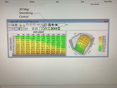
Here's a couple of pictures of a SO '09 MY OEM stock TQ Management DD TQ Request map demoing prior\post 3D smoothing application:
HPTuners 3D Map Smoothing Control.png HPTuners 3D Smoothing Control Applied.JPG
This uses the 4 corner settings in a map then it applies smoothing to all settings to\in between these map points according to the map's X-Y axis scaling to smooth out any irregular interpolation between the map points but not "drastically alter" the underlying scaling created by the interpolated map settings so the overall "file profile shape" is retained. Looking at the 2 pictures above you can clearly see the 3D smoothing being applied but the map's original profile scaling shape is retained.
What this does is help the ECU to smoothly "track" between all setting points within a map & all other maps within the tune calibration file at the same time, so the engine output doesn't give a "jittery feeling" response thus is smooth in all application.

I've gone back thru my final tune revision & applied this 3D smoothing to every finished 2D\3D map in my tune file that made sense to apply it to (practically all of them that doesn't do any direct airmass calc's or direct fueling calc's were fair game.....even some of the OEM stock maps were made smoother\cleaner by applying this 3D smoothing) then flashed it into ECU after getting car back from body shop yesterday & reinstalling all my louvers & hood deflector shield that I removed to test........

The results of doing this is worth it in spades.......the overall smoothness\integration\coordination of engine response across the board to all ECU inputs\outputs is night & day improved......doesn't provide any substantial increase--if at all--of any already gained peak HP\TQ from tuning but this cleans up the overall "driving feeling or experience" across the board from idle to WOT & everywhere in between.........especially when applied to the OEM individual cyl knock noise threshold sensitivity mapping......this really cleans up all the little .25*-.5*\sec cyl knock response blips from "jagged" interpolated knock sensor noise sensitivity threshold settings within the map's X-Y axis scaling....thus can gain you some marked improvement in available HP\TQ output under the curve by allowing the ECU to more accurately "ride the individual cyl knock noise sensitivity threshold curves" before calling cyl knock while under load when the knock sensors are active (especially if the Knock Mode in tune file is still set as Global--any single cyl knock detected results in spark timing getting pulled from all 8 cyls--as opposed to Per Cyl--any single cyl knock detected results in spark timing getting pulled from the affected cyl(s) only......Global is the OEM setting thus the gains will be more noticeable. My tune calibration file is set for Per Cyl knock mode....). This also works well w\ all Idle Control 2D\3D settings, too.

There are a lot of small "hidden gems" in HPTuners Editor software that can really enhance a tune calibration file's performance once found, understood then applied...........

I'm seeing this is best applied last, once all tuning has been completed & verified good\done, so you don't mess it all up by making further map setting changes.

An example of the little, sometimes overlooked & undervalued items in tuning that can provide real tangible benefits..........

Posted for those so interested............
 

JC SSP

Senior Member
Joined
Nov 8, 2022
Posts
1,060
Reaction score
457
Location
FL
Buddy you should really get into the tuning businesses…
 

GlassTop09

Senior Member
Joined
May 24, 2019
Posts
1,141
Reaction score
525
Location
Farmington, NM
Buddy you should really get into the tuning businesses…
JC SSP,

1st off, I have to say that I do sincerely appreciate you & your support of my meager abilities that I've learned in this endeavor of mine........so what I've typed below is in essence for you, out of respect, to have a better understanding of why I said what I've said earlier in this thread.......

But w\o going into detail, it is not financially feasible\desirable for me to go into any business endeavor w\ my retirement portfolio structured as is under the current tax laws.......the taxes incurred alone would cause me to lose money until I essentially have to double my current yearly AGI income to come close to making doing this a worthwhile endeavor.......I'm currently 63 yrs old on top of this so I'm no spring chicken anymore (got too many yrs of actual field work in the petroleum industry in San Juan\Rio Arriba Co in NM....1 of the most environmentally hostile work environments around.......really beats a body up physically over time) so also don't need or welcome the stresses of running a self-owned business...... As long as I remain within my currently structured portfolio, I'm good for essentially the foreseeable future (this is w\o figuring in any SS benefits).

So tuning is essentially a hobby to me to fill in some tinkering time. What I'm doing w\ this hobby concerning this BBS is to bring to light some of the things that I've seen\learned\discovered myself & from others to be errors, myths & false info in order to inform others on the consumer side.......from doing my own tuning on this 05-10 MY SO ECU.

After that, the rest is up to the individual to do with as they please..........

:beer:
 

JC SSP

Senior Member
Joined
Nov 8, 2022
Posts
1,060
Reaction score
457
Location
FL
I understand completely buddy.

Your level of tuning detail is incredible and would benefit many of us in the Mustang community.

God bless.
 

GlassTop09

Senior Member
Joined
May 24, 2019
Posts
1,141
Reaction score
525
Location
Farmington, NM
Does HPTuners use ECM Titanium?
No GriffX,

ECU Titanium is essentially the same type of tuning platform solution as is HPTuners, SCT, Hondata, etc.
The only difference is that ECU Titanium is centered around an "open platform model", ie 1 tuning software that can be used to access\modify\write tune calibration files across essentially every type of ECU calibration\OS made, whether OEM or standalone (their compatibility listings cover this very SO ECU).

So, IMHO, HPTuners has no need or interest in incorporating ECU Titanium into their own in-house developed software to do the exact same thing HPTuners is already doing.............the only difference is HPTuners isn't looking to access any standalone ECU's, only OEM ECU's.

From my perspective, when all the EPA smoke & fire clears, HPTuners will be 1 of the few tuning software platforms left standing to be a legal access avenue to tune an OEM ECU.

Hope this helps.
 
Last edited:

GriffX

Member
Joined
Sep 28, 2017
Posts
518
Reaction score
175
Thanks! I one tried to modify my bin file from a Siemens SIM4LE ECU with ECM Titanium and the UI looks similar to your screenshots. (ECM was not able to read my bin file, btw)

I have a specific question to your driver demand map. Lets assume I drive on a highway with 3000rpm and lift the trottle. Then, I go down the throttle position 16 row. At 1000rpm it is neg, so no fuel will be injected, at 740 it is 11 Nm (?). What is in between, lets say 900 rpm?
 

GlassTop09

Senior Member
Joined
May 24, 2019
Posts
1,141
Reaction score
525
Location
Farmington, NM
Thanks! I one tried to modify my bin file from a Siemens SIM4LE ECU with ECM Titanium and the UI looks similar to your screenshots. (ECM was not able to read my bin file, btw)

I have a specific question to your driver demand map. Lets assume I drive on a highway with 3000rpm and lift the trottle. Then, I go down the throttle position 16 row. At 1000rpm it is neg, so no fuel will be injected, at 740 it is 11 Nm (?). What is in between, lets say 900 rpm?
Ok.......according to Ford's calibration coding.........

Once you lift the APP & the A\D counts go to 0 (or in ECU it is .000), this tells the ECU that you're not wanting to continue applying a TQ request so the ECU goes into DFCO (decel fuel cut off thus the ECU shuts off the injectors so no fuel is being used) while the engine RPM's are dropping (ECU is still operating on dashpot throttle control & is using the BKT\MBT spark tables) until the RPM's reach 1,000 (this is the min RPM for dashpot throttle control & BKT\MBT spark timing control).

Once the RPM's go below this 1,000 RPM threshold AND the APP is still at 0 A\D counts, this tells the ECU that you want to go into idle adaptive throttle control (ECU then switches into idle adaptive throttle control from dashpot throttle control & switches out of BKT\MBT spark tables into idle feedback spark control), then the ECU will reactivate the injectors & tries to maintain the desired idle RPM's as set in the Idle Control section. The TQ request number that is set in the 740 RPM column at the 16 A\D count row in the TM DD TQ Request map is the max TQ request to apply during idle if needed to maintain the idle RPM's set (ECU now uses the airmass calc's off closed TB for rough idle control then uses spark timing for fine idle control) until the APP is depressed to start counting up A\D counts & once they exceed the 16 A\D count row, this tells the ECU that you want to start applying more TQ than requested at idle thus the ECU will now switch back into dashpot throttle control & activate the BKT\MBT spark timing tables to wherever the APP counts stop at........

Rinse & repeat......................

Hope this helps.
 

Support us!

Support Us - Become A Supporting Member Today!

Click Here For Details

Sponsor Links

Banner image
Back
Top