Lunati VooDoo #21270700 Camshafts

JC SSP

Senior Member
Joined
Nov 8, 2022
Posts
1,067
Reaction score
460
Location
FL
VE is the key! I have always built my engine set ups around this philosophy. I had mentioned engine as "Air Pump" in another post...

Most great engine builder from Smokey Yunick to John Lingenfelter have focused on VE to create great linear power (from idle to highest RPM). That broader power band incorporating precise shift recovery points to continue accelerating through the power band yields a very fast car that at any speed will get up and go!

Great to see that you are almost done with this tuning endeavor. With your expertise, I still think you should get into the tuner market...
 

GlassTop09

Senior Member
Joined
May 24, 2019
Posts
1,142
Reaction score
525
Location
Farmington, NM
VE is the key! I have always built my engine set ups around this philosophy. I had mentioned engine as "Air Pump" in another post...

Most great engine builder from Smokey Yunick to John Lingenfelter have focused on VE to create great linear power (from idle to highest RPM). That broader power band incorporating precise shift recovery points to continue accelerating through the power band yields a very fast car that at any speed will get up and go!

Great to see that you are almost done with this tuning endeavor. With your expertise, I still think you should get into the tuner market...
Absolutely correct JC SSP concerning VE.........is another reason why I can't understand why a lot of tuners don't have a VE checking software program in hand, especially the tuners who have access to a dyno. This DECS software I'm using only cost me $40.95 for the CD & all you need to use it is a graphing software like Forscan (or any PCM tuning software\interface) to capture the engine running IAT, RPM's, MAF & BARO readings at WOT to plug into the software & it spits it all out for you so you know how well the engine is BREATHING thru intake tract\EXHAUSTING thru exhaust tract thus it's max VE % output under real time operations using the very intake\exhaust components installed.......the KEY to total IC engine available & peak HP\TQ output! Cause if engine VE output isn't at least at 80%, there's something very wrong going on in either intake or exhaust tract that if it isn't rectified, it don't matter what else you're doing, you ain't getting nowhere but making all other issues worse!

Sure there are much more elaborate VE monitoring software systems available that can actually map out the engine's VE% per RPM's (also costs MUCH more.....AES has a very nice VE software\interface system that can map out engine VE at any RPM point & isolate the offending component(s).....for $1,700-$2,000 back in 2019) but all that is usually needed to be known for most automotive operational purposes is the engine's VE% output at WOT & max RPM's to know how engine should respond anywhere below WOT\max RPM's since below this point the engine's air intake will be controlled by TB TBA* being less than 82* (Ford uses 82* since the Ford designed twin bore concentric TB's 0* TBA stop is actually at 8* to eliminate the TB BF's from getting pinned to ID bore from upstream air pressure forces acting on the BF blades so the TB actuator motor can open the TB BF's w\ a fair sized deltaP across the BF blades from engine running so will actually be at 90*....parallel to incoming airmass flow thru TB--also the 2nd reason for the PCV system design existence on these 3V's.....this also limits the deltaP across the TB BF blades to keep it within the margins so the TB actuator motor can move the TB BF's off idle TBA easier w\o undue stress on the TB main shaft plastic driven\idler gearing..........remember this when you wanna start thinking bout getting rid of this PCV system, you might want to have a TB installed---like BBK's #1763 62mm TB---that you can readjust the TPS stop position to accommodate this issue outside of strictly within the tune......FYI) thus can be calc'd by the actual TB TBA* in use when less than WOT.
 
Last edited:

GlassTop09

Senior Member
Joined
May 24, 2019
Posts
1,142
Reaction score
525
Location
Farmington, NM
I think it is also a reason that these Ford engines don't need secondary air injection systems for emission reduction ?
I intended to answer this question earlier but got distracted..............

The reason why Ford (and others as well) don't need secondary air injection to provide the necessary O2 for the cats to use to oxidize the HC, CO & NOx (as well as not needing extra light off cats to heat up the main cats thus only need 1 cat for a single engine exhaust bank) is thru the invention of the 4-wire self-heating NB O2 sensor in conjunction to PCM calibration routines to cause these NB O2 sensors (and the current WB O2 sensors to cycle between rich\lean AFR) to switch around Lambda 1.0 to go rich\lean so PCM can actually interpolate the amount of rich AFR it sent in cats outside of stoich vs the amount of lean AFR (here is where the needed O2 for cat operations comes from) it sent into the cats outside of stoich to consume the rich amount it sent in prior along w\ the usage of cerium (an O2 storage\control medium) in the cats substrates to momentarily attract\hold this extra O2 sent in during the lean AFR cycle to treat the incoming rich AFR on the following NB O2 sensor switch to rich AFR outside of stoich at which time the cerium will release the stored O2 so the oxidation of the HC, CO & NOx can take place.....rinse, repeat. The job of the rear NB O2 sensor is to check the cat output for the presence of free O2 in exhaust post cat to inform PCM of 2 things: 1.) the condition of the cerium medium in cat substrate closest to engine during the pre-cat NB O2 sensor lean AFR switch.......and 2.) the cats ability to process the HC, CO & NOx in exhaust during the front NB O2 sensor rich AFR switch....by counting the number of rear NB O2 sensor readings that drop below stoich thus lean to a certain number of front NB O2 sensor rich\lean switches under 3 different sets of criteria during CL NM operations only to then calc the emissions CE ratio of the cats operation. The PCM, from reading the rear to front NB O2 sensor switch ratio, can actually adjust the amplitude & frequency of the front NB O2 sensors switching to control all this to maintain the cats at the most optimum CE ratio it can.......as long as all other engine components\systems integrity is maintained to prevent outside unmetered O2 entry & are operating properly as well.

Refer to pg 17, post 322 for further insight on the self-heating 4-wire NB O2 sensor operations & how PCM will use them in conjunction w\ engine fuel control & cat operation during CL (have a graph of the OBDII NB O2 sensor switching to illustrate this).............

This is what brought in what we now know (still are using currently) as OBDII emissions std in 1996.....a huge leap in automotive emissions processing from the 1st OBDI emissions std.
 

GlassTop09

Senior Member
Joined
May 24, 2019
Posts
1,142
Reaction score
525
Location
Farmington, NM
FYI....................

I just got a revelation on some tune setting operations that I'm not taking full advantage of.........especially during the winter months when the running engine ECT's\IAT's are usually lower than in summer months thus the engine can use a little extra added spark advance timing since colder, more dense air is usually more detonation friendly as is cooler engine ECT's meaning cooler combustion chamber temps.
I realized that this is precisely what the Ford engineers intended thru the lower end of the Spark Advance\BKT Corrections\ Base IAT\Multi & Base ECT\Multi map settings to take advantage of.

The upper end of these maps are intended to PULL spark advance timing from the base BKT spark advance timing map settings in use when running engine IAT\ECT temps go up past the set upper operating temp threshold deadbands in these maps thus cutting available HP\TQ accordingly due to the increased tendency for detonation to occur........but in the same breath, when the running IAT\ECT temps go down below their lower operating temp threshold deadbands, these are intended to ADD spark advance timing to the base BKT spark advance timing map settings as also set in these maps thus increasing available engine HP\TQ accordingly due to lower operating temps being more detonation friendly & do both w\o having to use the KS spark advance timing reacting off cyl knock so this is always available to offset any additional spark advance timing added from these BKT Corrections\Base IAT & ECT Temp maps that set off any cyl knock as per the usual designed operation of the KS applied knock spark advance timing above the combined base BKT spark advance timing map settings.
I just realized that, due to the way I have all this currently set up between the MBT vs BKT base maps in my tune file, I've actually locked the PCM out of adding any additional spark advance timing based off lower running IAT\ECT across the board thus am missing out on free extra available engine HP\TQ!

Now we can't have that going on since I'm now aware of this........so I've just got done w\ Per Cyl Mode tune revision #10 to fix this by going into the base MBT spark advance timing map & adding 1* across the entire map so this creates a 5* gap between the base BKT spark advance timing map vs the base MBT spark advance timing map, then I went into the Knock Retard\Maximum\Max Advance map & reset this map settings from 8* to 4* across the entire map.....doing this retains the 4* spacing for KS applied spark advance timing I had set prior using the base MBT vs base BKT map settings alone, but this now creates an additional 1* spacing between the total base BKT\BKT VC + KS spark advance timing vs the total base MBT\MBT VCT spark advance timing for PCM to now use to add any additional spark advance timing calc'd based off any running engine IAT\ECT that is below the low IAT\ECT temp deadband thresholds corrected by their corresponding multiplier maps......thus adding free additional available engine HP\TQ across the board as PCM sees the need to add it based off lower running IAT\ECT, up to the 1* max as physically set by the new spacing I've created between the BKT added KS max spark advance timing map's 4* & the base MBT spark advance timing map's 5* spacing off the base BKT spark advance timing map (MBT 5*- KS 4* = 1* spacing for PCM added additional spark advance timing from lower operating engine IAT\ECT only during winter months)!

Example of this in operation below:

Since the ECT thermostat is going to limit the lower ECT to 195* below the 200*F -- 0* spark timing deadband threshold, I set the lower 140*F ECT threshold at 10* spark timing thus the 60*F temp difference will create a multi of .17* spark timing for every 1*F below 200*F thus 200*F -195*F = 5*F * .17* SAT multi = .85* SAT * multi derived from engine load & RPM's so say .30 load\2,750 RPM's so multi of .070 * .85* SAT = .06* added ECT SAT.
Now if running engine IAT is also at 30*F.......10*F below the upper IAT 40*F -- 0* SAT deadband threshold, now the next lower IAT 0*F -- 20* SAT threshold thus creates a multi of .5* SAT per 1*F below 40*F thus 40*F -30*F = 10*F * .5* SAT multi = 5* SAT * multi derived from same engine .30 load\2,750 RPM's so multi of .071 * 5* SAT = .36* added IAT SAT so .36* IAT SAT + .06* ECT SAT = .42* total IAT\ECT added SAT to combined base BKT\BKT VCT + KS SAT in the new additional 1* spacing created between the base BKT\BKT VCT\KS max SAT vs base MBT\MBT VCT max SAT & PCM will automatically increase\decrease all this according to changing engine load\RPM's & changing operational IAT\ECT on the fly up to a max of 1* above all max combined base BKT\BKT VCT + KS max SAT--thus taking advantage of the benefits of lower engine operating IAT & ECT when environmental conditions allow for it & at the same time maintaining the PCM code logic process of BKT SAT (the floor) not crossing\exceeding MBT SAT (the ceiling) at any point in engine operations across the board......just as it is currently operating now!

Just taking full advantage of every feature available in this SO PCM's calibration so its operation is made as fully dynamic as the calibration allows to optimize engine drivability\performance fully & not leave any free available HP\TQ untapped as environmental operating conditions allow.........like right now!

After this revision is flashed in, its fully done tune-wise as now all PCM calibration provided features within the tune file are being utilized to their fullest potential.
 

Juice

forum member
Joined
Aug 24, 2017
Posts
4,622
Reaction score
1,904
I seem to recall you called it "done" atleast once already.... lol
 

GlassTop09

Senior Member
Joined
May 24, 2019
Posts
1,142
Reaction score
525
Location
Farmington, NM
FYI.....................

Got tune revision Per Cyl Mode #10 flashed in & made my std DC route w\o making any WOT run as I already know how it'll go. Car drove fantastic thruout the DC........PCM seemed really responsive in operation thus the engine operation followed suit. The 4th gear 2,500 RPM to limiter WOT run I did @ 2-22-23 must've really cleared this engine's throat so to speak as she was really responsive to any throttle inputs made during this DC..........so I guess Italian tune-ups really do work! :driver:;)

Got back home & replayed datalog.......the only thing I could see was that, since resolving the KS mic to cyl assignment issue in tune, the KS mic voltage signal traces are much, much cleaner & now I can definitely see thru these KS mic traces when the PCM energizes the VCT solenoids at the start of any VCT cam retard commands, where the VCT is commanded to advance the cams back to 0* & whenever the PCM sends commands for a VCT cam timing readjustment......like clockwork the KS mics responded to the VCT solenoids clicking when PCM commands them to move. This IMHO is definitive proof of the #2\#6 KS mic reassignment cleaning up the engine firing order sequencing to KS mic voltage tracing pattern so PCM can easily distinguish all other generated engine noise from the cylinders when they fire the plugs as the KS applied per cyl spark advance timing traces all cleanly laid over each other when advanced off BKT floor\retarded to BKT floor & also traced cleanly over each other when at the full 4* max advance thruout the datalog. I think this was assisted by the resetting of the KR\Maximum\Max Advance map settings from the 8* I had set prior (this KS SAT setup used the PCM calibration code logic process to run combined base BKT\BKT VCT + KS max SAT continuously up against the base MBT\MBT VCT SAT w\o exceeding it when the KS came online) to 4* max across the board & increased the base MBT SAT map settings by 1* across the board (this separated the base MBT\MBT VCT SAT from the combined base BKT\BKT VCT + KS max SAT to create the necessary 1* spacing for PCM to add in any low IAT\ECT BKT SAT correction it deemed necessary).....but this spacing also gave the PCM TQ Management an extra 1* SAT to use in its TQ calcs across the board which can explain the increased engine response I was feeling. This setup also now isolated the KS applied max SAT from the base MBT\MBT VCT SAT so released some PCM EPROM cycles from having to constantly readjust the combined BKT SAT to remain just under the MBT SAT during KS deployment which had to help PCM speed up processing tasks elsewhere.

Checked the engine IAT\ECT channel graphs & saw that during this DC the IAT never went below 40*F (lowest it got was 41*F @ 68 MPH.......AAT's were in the mid 50*F range today) so PCM never deployed any BKT IAT corrected SAT but we did deploy some BKT ECT corrected SAT during most of the DC......dropping out only when in 5th gear lugging up the 2 steep inclines (engine ECT climbed from 194*F to 208*F) but ran between 194*F- 198*F the rest of the DC so added between approx .012*-.071* extra ECT BKT corrected SAT......the majority of this should come thru the BKT IAT corrected SAT when it crosses below the 40*F threshold.

All in all, a good move on my part to redo this in my tune file.......................

Have put all tuning equipment in my diag tote bag & hung up for the foreseeable future. Have all these tune files\datalogs transferred to my main computer for access purposes. Will be using my trusty Foxwell NT301 scan tool to monitor her from time to time going forward.

Moving on...............I do still have 2 Anchor engine motor mounts to install when the weather gets warm enough.

Time for this.............:driver:
 

GriffX

Member
Joined
Sep 28, 2017
Posts
525
Reaction score
177
Thank you for your explanations, I enjoy them very much. Last video was surprising.

I have a question regarding a supercharged Mercedes M111 engine, which I increased the boost form 4 to 8 psi (mechanically 12 psi would be possible). Engine did 80k Mi without any errors on higher boost.
Now I did a 100k Mi engine checkup.

- Ignition coils (old had cracks)
- spark plugs
- filters
- supercharger belt tensioner (had slippage)
- cleaned fuel injectors (changed from 2 rays to fog spray pattern)
- cam chain tensioner spring (was worn, clicking during startup)
- measured chain wear and compression
- O2 sensor in front of cat (Bosch)
- measured the MAF (compared to old data, still ok)

Engine is running smooth on idle like new, no error codes.
But, engine noise changed under medium to high load to a rough, raspy tenor. I was thinking that I probably damaged the exhaust manifold when I removed the O2 sensor, it is known to get cracks, It is made from stainless steel sheets. Did not find any leakage. So I decided to wait for something to happen.

Today I inspected the spark plugs after 8k mi. They are NGK iridium fine wire plugs, so the color is not so related to mixture as normal plugs, but they are white.

Now I was thinking that the raspy noise could be a more lean condition than before. Is it possible that a new O2 sensor from Bosch has a different calibration curve than the OEM (which is also manufactured by Bosch) and pushing the engine to lean?

Thanks!

Screenshot 2023-03-04 194506.png
 

GlassTop09

Senior Member
Joined
May 24, 2019
Posts
1,142
Reaction score
525
Location
Farmington, NM
Thank you for your explanations, I enjoy them very much. Last video was surprising.

I have a question regarding a supercharged Mercedes M111 engine, which I increased the boost form 4 to 8 psi (mechanically 12 psi would be possible). Engine did 80k Mi without any errors on higher boost.
Now I did a 100k Mi engine checkup.

- Ignition coils (old had cracks)
- spark plugs
- filters
- supercharger belt tensioner (had slippage)
- cleaned fuel injectors (changed from 2 rays to fog spray pattern)
- cam chain tensioner spring (was worn, clicking during startup)
- measured chain wear and compression
- O2 sensor in front of cat (Bosch)
- measured the MAF (compared to old data, still ok)

Engine is running smooth on idle like new, no error codes.
But, engine noise changed under medium to high load to a rough, raspy tenor. I was thinking that I probably damaged the exhaust manifold when I removed the O2 sensor, it is known to get cracks, It is made from stainless steel sheets. Did not find any leakage. So I decided to wait for something to happen.

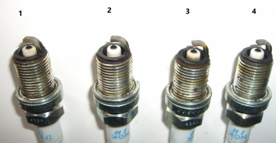
Today I inspected the spark plugs after 8k mi. They are NGK iridium fine wire plugs, so the color is not so related to mixture as normal plugs, but they are white.

Now I was thinking that the raspy noise could be a more lean condition than before. Is it possible that a new O2 sensor from Bosch has a different calibration curve than the OEM (which is also manufactured by Bosch) and pushing the engine to lean?

Thanks!

View attachment 86039
Hi Griffx,
Going off your info in your post, I'd be less concerned about the Bosch O2 sensor being that far off (typical mass produced manufacturing QA\QC tolerance is 3% random batch sampling) & more concerned w\ the fuel injectors and\or air filter (if this was also changed) concerning any lean A\F mix issue w\ your engine............the idle info you gave IMHO is an indication of no major issues, but I'd suggest to just monitor the ECU live data over time to see if there is really a legit concern.........the ECU may need some time to fully readjust.

Concerning your fuel injectors, what are you meaning by "changed from 2 rays to fog spray pattern"?

Looking at the spark plugs, 1st question.......are ethanol-based fuels being used in Germany? If so, then as a general rule, the plug center electrode porcelains will for the most part be\stay white if A\F is close to\at Lambda 1.0 (ethanol is alcohol-based which has no carbon in its molecular chain) so what I focus on is the ground strap's color....... #1, #2 & #4 plugs look good to me but #3 shows some moderate carbonizing deposits on center electrode porcelain\ground strap.......I would guess that #3 cyl sees the majority of any PCV return flow (I also see a slight hue of this darker coloring on #1 plug's center electrode porcelain, but it is not showing a heavy ring pattern as #3 plug is---#3 plug is not firing as hot as the others........this is why the deposits are forming. I see you changed ignition coils, but you might have a 2nd look at them.......I'd swap #4 & #3 ign coils, run engine for a spell then pull plugs to see if this staining moves to #4 plug......will verify the #3 coil is firing weak & needs replaced). Was the higher flowing fuel injector in #3 cyl (this can indicate that this cyl was running a little richer than the rest)? or were all of them flowing relatively even when cleaning them?

This is what I'm picking up on from the info you've posted, not so much an issue w\ your new Bosch O2 sensor.

Hope this helps.
 

GriffX

Member
Joined
Sep 28, 2017
Posts
525
Reaction score
177
Helps a lot. I changed to 91 with 5% ethanol last year when the price for 93 ethanol free reached 8.90$/gal
(91 was 8$, today it's 7.05$). The 91 here is horrible in carburetor engines, my generator and chain saw are hardly running with a bit older fuel.

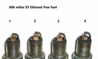
I attached picture of the old spark plugs 60k mi driving on 93. The spray pattern of the cleaned injectors looked like a typical fine spray after cleaning (like videos on youtube), but I cannot say if all have similar throughput. Must think about a DIY measurement.....

I will switch the two coils. The Siemens ECU has only the k-line connected to the OBD port, the data log is very slow, I can see that the O2 voltage starts to drop from 4800 rpm on and air mass is steady at 168 g/s. Not sure if the MAF is working on higher flow (specified max 185 g/s). I usually don't rev more than 5k anyway.
I can read and write the ECU but cannot modify the hexdump. The Siemens ECU has the x,y axis data separated from the z values and I did not find the jump pointers to connect them and gave up.

Thanks for your help!

Screenshot 2023-03-06 153645.png
 

GlassTop09

Senior Member
Joined
May 24, 2019
Posts
1,142
Reaction score
525
Location
Farmington, NM
Helps a lot. I changed to 91 with 5% ethanol last year when the price for 93 ethanol free reached 8.90$/gal
(91 was 8$, today it's 7.05$). The 91 here is horrible in carburetor engines, my generator and chain saw are hardly running with a bit older fuel.

I attached picture of the old spark plugs 60k mi driving on 93. The spray pattern of the cleaned injectors looked like a typical fine spray after cleaning (like videos on youtube), but I cannot say if all have similar throughput. Must think about a DIY measurement.....

I will switch the two coils. The Siemens ECU has only the k-line connected to the OBD port, the data log is very slow, I can see that the O2 voltage starts to drop from 4800 rpm on and air mass is steady at 168 g/s. Not sure if the MAF is working on higher flow (specified max 185 g/s). I usually don't rev more than 5k anyway.
I can read and write the ECU but cannot modify the hexdump. The Siemens ECU has the x,y axis data separated from the z values and I did not find the jump pointers to connect them and gave up.

Thanks for your help!

View attachment 86074
These plugs are indicative of the way they should look when an ethanol-free fuel is used.

Now since you've posted that you were running E0 93 oct fuel prior then switched to E5 91 oct fuel, remember that the fuel stoich AFR is different between the 2 fuels (E0 93 oct @ 14.64\14.7:1, E5 91 oct @ 14.4:1), so if your car's ECU was tuned on E0 @ 14.7:1 or 14.64:1 (this would be entered in ECU's fuel stoich setting to use in the ECU's EQ Ratio Lambda equation to calc fuel according to air load calc'd to arrive at Lambda 1.0) & you change to an ethanol based fuel w\o correcting this in the ECU, just know your O2 sensor readings will change to show a more lean A\F mix (ECU added fuel) due to the ECU not accounting for the extra O2 that is present in ethanol (ECU is using the fuel stoich AFR for E0 to calc fueling for E5 thus cannot account for it) so the O2 sensors will pick this extra O2 up thus will show a leaner A\F thus ECU will adjust & increase extra fuel to compensate. So, until the fuel stoich AFR is corrected in ECU's EQ Ratio Lambda equation to match the fuel stoich AFR for E5 91 oct fuel, you'll always see this offset in O2 sensor feedback. The engine is really not lean at all per se, if anything it will be slightly rich due to fuel over correction from ECU trying to correct E5 91 oct fuel using E0 93 oct fuel stoich AFR.

FYI...........

PS edit--You also might be aware of potential for detonation since the E5 is 91 oct vs the E0 being 93 oct (this has a higher resistance to knock).
 

GriffX

Member
Joined
Sep 28, 2017
Posts
525
Reaction score
177
That's good to know.

The OEM tune right now is for 91E0 @ 4 psi boost, engine runs with 91E5 @ 8 psi.
This rough running noise at higher load was independent from fuel, so, will just wait and see. I already taped an old cell phone under the hood and recorded the noise :).

Do you know if there is a life span for knocking sensors? It is basically a microphone? Unfortunately I cannot read out the knocking sensor with OBD and I have no idea how detonation sounds.

Regarding your PCV assumption that #3 gets more, I've seen that there are 2 PCV outlets, between 1,2 and 3,4 and the outlet is closer to 1 or 3 than 2 or 4. It's behind the injectors in front of the valves.

Thanks !
 

GlassTop09

Senior Member
Joined
May 24, 2019
Posts
1,142
Reaction score
525
Location
Farmington, NM
Do you know if there is a life span for knocking sensors? It is basically a microphone? Unfortunately I cannot read out the knocking sensor with OBD and I have no idea how detonation sounds.
No, I don't know this or have found any info to date that gives any insight into this. I do know that these sensors can wear out over time just like any other analog piezo device will & lose their sensitivity or completely fail (in my case I had 1 OEM KS mic to drastically lose sensitivity over a 14 yr span causing a severe loss of cyl knock detection on 1 bank, but not enough signal voltage degradation to fail & throw a MIL DTC.......only way I caught this is due to me running datalogs\recording the data while tuning my own engine. This is 1 instance of what waiting on a PCM\ECU MIL DTC to alert you of an issue can get you into w\ these modern PCM's\ECU's......there's still no substitute for periodically DIY actual component tests\checks for operational integrity), so you'll have to play these by trial & error.......or treat them as an expendable item (due to their importance in engine safety protection) & just replace them in a certain amount of time to ensure their "freshness" or periodically test their sensitivity\voltage signal output using a DMM (digital multimeter) for any hint of sensitivity loss\voltage output loss to determine if\when to replace them.

On some engines, this is easy to do since open access to the KS mics is very good......on others (like these Ford Mod Motors.......) open access to the KS mics\connectors is not available so presents another wrinkle as you'd have to remove the IM to access these KS mics\connectors & due to this, it may be a better all around move to just replace them whenever you have the IM removed after they've been in service over a certain amount of time.

PS edit--To get an idea of how cyl knock sounds, check out several YT videos on TunerNerd Pro knock sensor control system usage.....
 
Last edited:

GriffX

Member
Joined
Sep 28, 2017
Posts
525
Reaction score
177
One more question for curiosity, back in the days when I tried to understand the Siemens ECU I think I could identify the driver wish map. It had x,y,z which was ca. 12 by 12 by 12 dimension, the pedal position readout had 100 digits. Is there some kind of interpolation from the high resolution of the pedal to the driver wish map?
Thanks!
 

GlassTop09

Senior Member
Joined
May 24, 2019
Posts
1,142
Reaction score
525
Location
Farmington, NM
One more question for curiosity, back in the days when I tried to understand the Siemens ECU I think I could identify the driver wish map. It had x,y,z which was ca. 12 by 12 by 12 dimension, the pedal position readout had 100 digits. Is there some kind of interpolation from the high resolution of the pedal to the driver wish map?
Thanks!
Assuming that you're now referring to the Ford SO PCM...........................

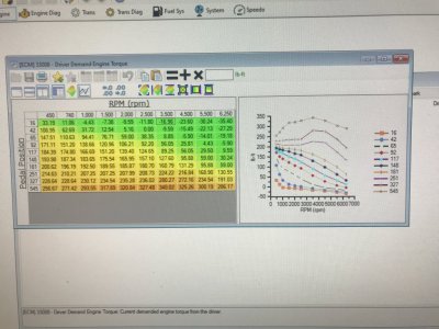
Here provided below is the Ford SO PCM's OEM TQ Mangement's Driver Demand TQ Request map:
Stock DD TQ Request map.JPGThis map uses the APP's actual A\D count output derived from driver input thru APP to instruct PCM of the amount of engine TQ requested to apply according to engine RPM's.

The SO PCM is programmed to scale A\D counts from .000 to 1.000 thus comes out to 1023 scale, so on every KOEO, the PCM will recalibrate 1 set of the potentiometers at rest APP A\D count output to rep .000 then the other set of the potentiometers at rest APP A\D output to rep 1.000 thus 1023 scale so any APP output from here on will scale accordingly so the full APP voltage travel output will equal 1.000 or 1023 redundantly (so if 1 set of APP potentiometers fail, the other is a backup so DBW system continues to operate).

Hope this helps.
 

GriffX

Member
Joined
Sep 28, 2017
Posts
525
Reaction score
177
Let's say engine has 2000 rpm and I push the pedal to 130. What value the PCM gets? 139 or 165 as torque demand?
Background of my question, because of ......politics, large areas in the city are 19 MPH zones. I'm not able to drive 19 MPH in 4th gear. It is 17 or 21 with constant pedal push, like I am at a digital step in the (tuned) PCM.
 

GlassTop09

Senior Member
Joined
May 24, 2019
Posts
1,142
Reaction score
525
Location
Farmington, NM
Let's say engine has 2000 rpm and I push the pedal to 130. What value the PCM gets? 139 or 165 as torque demand?
Background of my question, because of ......politics, large areas in the city are 19 MPH zones. I'm not able to drive 19 MPH in 4th gear. It is 17 or 21 with constant pedal push, like I am at a digital step in the (tuned) PCM.
Yes, you may very well be seeing\feeling the PCM performing interpolation between any 2 map data points according to the input data it receives from all input sensors to make any adjustments to TQ output to try to maintain the requested TQ output based on the APP\RPM position.......if you're controlling the APP w\ your foot.....remember DBW's primary\secondary design attributes are also in play so the PCM can divorce the TB movement from the APP when it sees the need to do so to maintain a TQ request so the response can seem to be stair stepped at times.....for lack of a better way to explain this.

Cruise control as a general rule is usually better at MPH speed control because it can stabilize\lock the APP input signal thus helps w\ PCM adjusting the TB outputs smoother as the PCM isn't getting fluctuating APP A\D count inputs which are creating more constant PCM TQ recalculations.......any APP A\D count change will trigger a new TQ request......just the nature of the beast.

How well these maps are setup, programmed & most importantly, interpolation is smoothed out between any data points by tuners will play a BIG part in how they'll FEEL to the driver, as this is what controls the PCM application of all outputted map data.

This goes for ALL maps in tune files.......not just the Driver Demand TQ Request maps alone.

PS edit--Also, how smoothly the APP input signal is applied will also have an impact on all this as well.......if this input signal is blocky\spiky the PCM thru DBW will be trying to imitate the ETC APP throttle signal thru the ETC TB TPS% control.............
 
Last edited:

GlassTop09

Senior Member
Joined
May 24, 2019
Posts
1,142
Reaction score
525
Location
Farmington, NM
How well these maps are setup, programmed & most importantly, interpolation is smoothed out between any data points by tuners will play a BIG part in how they'll FEEL to the driver, as this is what controls the PCM application of all outputted map data.
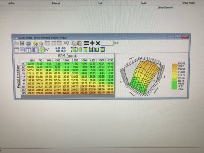
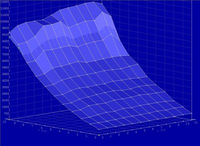
In hindsight, I should've posted this same map in 3D chart provided below (the often mentioned "histogram") instead of in 2D chart as when in 3D chart, you can get a much better sense of how data point interpolation\smoothing can come into play concerning PCM calc's of data between 2 or more known data points within a map to create driver "feel" thru engine response\performance derived from this control mapping......which also is relevant w\ any other in-tune control mapping using an X-Y axis.
IMG_0759.JPGIMHO, it is how well a tuner 1.) maintains the Ford-tuned map interpolation\smoothing between any map data points changed along w\ the Ford-tuned X-Y axis set in any map to retain the already driver accustomed "feel" or 2.) how well the changed map data points are smoothed\interpolated into any existing map data points interpolation\smoothing to not create any offsetting or "out of place" feel thru engine response from PCM calculation\application is 1 of the main criteria that determines a tuner's abilities or "worth" in a majority of customer's POV...........why you often read\hear the phrase " I want to get increased HP\TQ but also to drive like stock".

This is why a tuner who tunes using a dyno, then doesn't make a data logged test drive of their finished dyno tuning to check drivability afterwards before returning the vehicle, are often the ones who get hit w\ a lot of complaints\returns post tuning sessions....vs a remote tuner who is tuning using actual driver initiated datalogs of engine response\performance from real world driving conditions along w\ actual driver habits recorded thru the ETC APP\TB TPS DBW control........IMHO is 1 of Lito's strongest strengths as I'm positive he is putting in much more effort to interpolate\smooth his tune mapping changes so they "feel" just as good to the driver from a behavior standpoint along w\ any net gained HP\TQ output than others.

Is also what I spent a lot of time doing to my tuning as well so all feels as good & clean transitioning from idle thru WOT & back as I could make it while at the same time safely increasing the HP\TQ output as best I could thru street tuning.

This takes a LOT of time to develop\get right in a tune, especially for a 1st time DIY'er.
 

GriffX

Member
Joined
Sep 28, 2017
Posts
525
Reaction score
177
Thanks, I did a comparison between a 4 psi and a 12 psi mail-in tune, but was not able to identify the maps, only a few data lines were changed. For me, driveability is much more important than 5 HP more. Very unpleasant to drive are the downsize Diesel engines. Had a 1.4l manual form VW for a week, was mileage optimized but awful in city driving.

This was one of my unidentified maps form the Mercedes supercharged engine. The upper points are for 12psi. So only the last 2 lines were modified:
IMG-20170308-WA0004.jpg

The Siemens ECU has separated areas for x,y and z-values in the bin file, very annoying. I gave up and drive the engine with 8psi, which is an working value without the necessity to modify the stock tune.
 

Latest posts

Support us!

Support Us - Become A Supporting Member Today!

Click Here For Details

Sponsor Links

Banner image
Back
Top