Lunati VooDoo #21270700 Camshafts

JC SSP

Senior Member
Joined
Nov 8, 2022
Posts
1,068
Reaction score
460
Location
FL
Directly from Ford Racing...

Whenever the TracKey is used to start the vehicle, many engine control characteristics are changed to be more suitable for track use. These include: • Ignition timing • Twin Independent Variable Cam Timing (TiVCT) • Wide-Open Throttle fueling • Engine braking • Accelerator pedal map • Idle speed • Throttle response • Cooling fan activation temps • Skip-shift disable (2012 only) In addition, the following features are unique to TracKey: • Driver adjustable Launch Control, or "2-step engine speed limiting" • Driver adjustable Pit Lane Speed Control • Lopey idle
 

Attachments

  • TracKey_Customer_Instructions_V2.0.pdf
    548.4 KB · Views: 2

GlassTop09

Senior Member
Joined
May 24, 2019
Posts
1,142
Reaction score
525
Location
Farmington, NM
FYI..............................

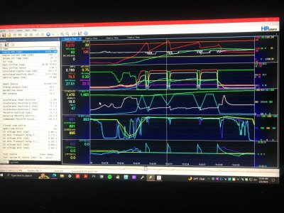
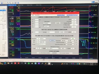
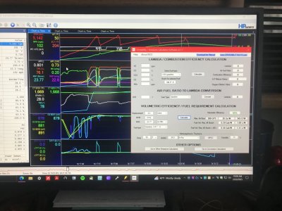
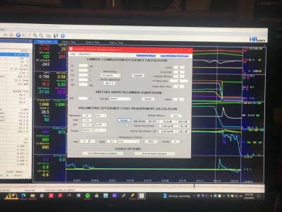
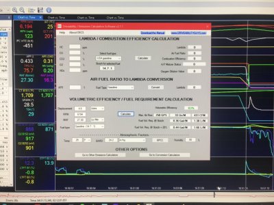
Was going over the last data log data to get a sense of how engine was fairing from a VE POV, so I ran my copy of DECS (Drivability\Emissions Calculations Software v2.1.1) software to calc engine VE capacity at a couple of points during the WOT run.
Note: In the VE calculator section, the authors didn't provide for adjusting the gasoline stoich so all this is using the std stoich of 14.7:1......but since this reps Lambda 1.0 & the SO PCM is using the EQ Ratio Lambda formula w\ the correct fuel stoich of 14.08 for its calcs, then will assume that the resulting VE calc'd data is still relevant.............

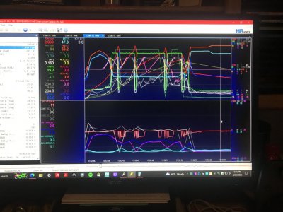
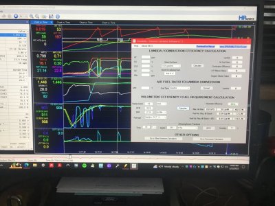
Here's a couple of shots of engine airload data @ top of 2nd gear where I then shifted into 3rd gear & the VE calcs derived from the data:
Final Tune Revision WOT 2nd Gear 2-1-23.JPG Final Tune Revision WOT 2nd Gear VE Calcs 2-1-23.JPG
The industry std acceptable VE% for good engine breathing is 80% VE.........so my old now 164,105 mi 4.6L V8 w\ these Lunati VooDoo #21270700 cams, OEM Bullitt 83mm CAI & MF #5461336 cats installed is breathing quite well @ 84% VE @ 421 CFM........we ain't at the 6,500 RPM limiter yet either.

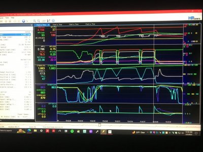
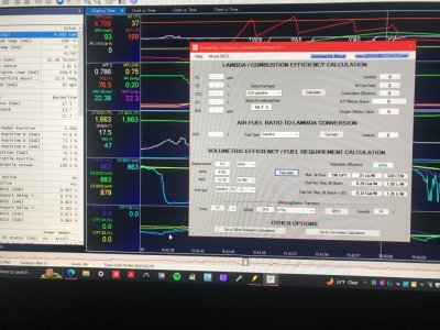
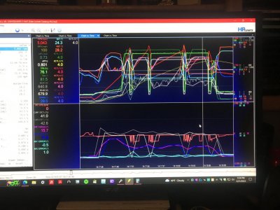
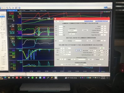
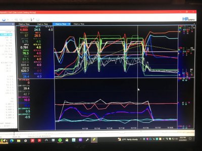
Here is another set of pictures taken at top of 4th gear where I let up due to excessive tramlining & the VE calcs derived from the data:
Final Tune Revision WOT 4th Gear 2-1-23.JPG Final Tune Revision WOT 4th Gear VE Calcs 2-1-23.JPG
Note here that the IAT change had an impact on the VE calcs even though the engine RPMs thus MAF lbs\min were lower..........just a 2*F change in IAT resulted in a VE% increase of 5% from 84% to 89%.

PS edit--Here's proof of why you want to route all air flow into the CAI from the front side of radiator core support.........whether NA or FI. Also, why I'm wanting to swap in the Ford OEM CAI from a '10 GT as this CAI is THE 1 to use on all NA 4.6L 3V's (all air entry is from front of rad core support thru its snorkel & uses a 85mm MAF housing for excellent MAF signal resolution while moving more than enough air mass you'll ever need for max performance gains AND is a LEGAL CAI for EPA purposes since this CAI is designed for this VEI EFN# 9FMXV05.4VEK which covers ALL 05-10 GT's w\ a 4.6L V8 installed & is an OEM Ford factory part that has legal EPA CoC signoff).

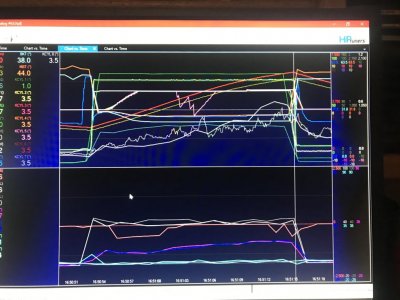
You'll also note in both sets of shots, the air load calcs essentially looked to have flatlined at .75 load-.76 load as engine RPM's were increasing.......this data clearly shows that the Ford OEM '08-'09 Bullitt 83mm CAI equipped w\ a K&N E-1997 Bullitt air filter w\ a dust sock installed over it isn't restricting any air mass flow into engine (you should have seen air load actually starting to decline as engine RPM's increase due to the increased air mass frictional drag coefficient off increasing airflow velocity thru MAF housing\CAI tube\TB\IM runners.....)......the air load calcs are actually slowly increasing as engine RPMs are going up (can be seen clearly when panning the MAF lbs\min graph line.....) & as in the 1st set of shots, we ain't nowhere around the 6,500 RPM limiter either.........so until the 6,500 RPM limiter is reached under full WOT in 4th gear, we won't know the actual final results, but from looking at this data, it appears to me that what I see here is primarily the engine cyl heads along w\ the Lunati's camshaft profile off the current VCT cam retard angle% in use is dictating the air mass VE profile thru the engine........which is exactly where you want this to be dictated from........means that I, the tuner, is in control of this (VCT cam retard was at 18* in the 2nd gear shots, VCT cam retard was at 15* in the 4th gear shots....PS edit--VCT is set for max cam retard of 20* @ 6,500 RPMs so it ain't at full capacity either.....FYI) & that the MF #5461336 CARB-cert TWC aftermarket cats aren't creating any excess back pressure\deltaP thru exhaust (Kooks 1 5\8" LTH's\X-pipe into Pypes Super Bomb Mid Muffler catback exhaust system) to negatively affect the VE% air mass flow rate thru the engine.

Some of what you're seeing here is from me short shifting engine between 5,500-6,000 RPMs during this WOT run to keep from hitting the 6,500 RPM ETC soft limiter as I have done on earlier occasions trying to go off using 6,000-6,100 RPMs as shift points which causes the TB to swing closed twice during gear shift transition instead of once, throwing all off kilter.....especially fueling......causing the PCM to have to reinitialize from WOT into CL-NM then back into WOT 2 times during the 1 gear shift (engine RPMs will easily flare up the 400-500 RPMs extra & cross the limiter during the gear shift).......this is the reason why\for the N2MB WOTBox's existence to provide a no-lift throttle shift using spark cut to momentarily drop engine RPM's to facilitate gear shifting but keep PCM fully in WOT operations once initiated to stop the WOT to CL back to WOT cycling.......that Ford (or someone who has access to the Ford calibration source code.......hey HPTuners......) could have resolved w\ a simple timer installed in PCM calibration coding to delay the WOT Disable process long enough (10 secs is more than enough) for the ETC throttle control to make the round trip signal swing during gear shift to get back into WOT position before timer count off so PCM never momentarily cycles out of\back into WOT during driver intended WOT operations.

Oh well, it is what it is............ain't gonna use any spark\fuel cut limiter going forward (IMHO is the main reason why the majority of timing component damage\oil pump damage w\ these Mod Motors that you'll never see if kept primarily on the ETC soft limiter.........) ......especially if primarily street driven as my car is going to be.

Ok I'm done...........off to bed...........
 
Last edited:
Joined
Jan 12, 2023
Posts
97
Reaction score
21
Location
Minot, ME
Thanks much Juice and JC, no wonder nobody could explain. Good answers, seem to have more questions sometimes as maybe a few solutions.

GlassTop- Your info is priceless, sorry on my interference here. Just keep thinking of “well what if” or “how about this”. Yes I know, problem has been brain engagement right along…
 
Last edited:

GlassTop09

Senior Member
Joined
May 24, 2019
Posts
1,142
Reaction score
525
Location
Farmington, NM
the air load calcs essentially looked to have flatlined at .75 load-.76 load as engine RPM's were increasing
Duh......this is due to the PCM's TQ Management using the mechanical TQ available (current trans gear ratio, rear axle gear ratio & tire revs\mi off tire dia along w\ the current RPMs off trans OSS to then compare to engine RPM's off CKP sensor) to calc the necessary engine air load thru ETC TB PTA & EA\SD\LWFM predictive\MAF actual calcs to provide the necessary engine TQ output needed to maintain\hit the 545 row of driver WOT TQ requested at the current engine RPM's thus maintain the RPM thus MPH.......... it's flatlining due to this TQ calc being all the PCM needs to maintain the status quo......

Forgot for a moment about this SO PCM being a primarily TQ based engine management system...........

If you look in all the pictures at the top section's white graph line........this is the IPC WTE graph that checks both of these for agreement. You'll note that on every gear shift, you'll see the IPC WTE graph drop below the 0 ref line (neg WTE's) for a moment then return to the 0 line.......this is due to the ETC predictive airload calc being higher than the actual MAF calcs due to TB BF cycling then once the TB BF's are back at full WOT position the MAF calcs realign back to the ETC predictive calcs thus are in agreement once again.

This is why you NEED to apply increased transient accel gain & time constant fueling (the carb version of accelerator booster pump or power valve) to make up for this to prevent engine stumbling from being momentarily leaned out during WOT...................MAF side is reactive to actual TB's PTA\EA sizing during TBA operation, not proactive in all ETC TB operations.......why you NEED SD & proper ETC TB PTA\EA map data for the actual TB's physical size being used as well as SD is proactive when using the LWFM air load tables to mimic actual MAF calcs off physical TB's PTA\EA sizing until MAF catches back up, thus can be used in ETC predictive airload calcs to close this gap but even this isn't fast enough to counter a 62mm TB's near instant air mass changes when it's BF's are swept open\closed....

FYI for those so interested...................
 
Last edited:

GlassTop09

Senior Member
Joined
May 24, 2019
Posts
1,142
Reaction score
525
Location
Farmington, NM
FYI...................

Been thinking thru some things since my last posting in post #405 concerning transient fueling accel gain\time constant mapping w\ a FP 62mm TB vs the OEM 55mm TB (which the OEM '09 GT stock tune's transient accel gain\time constant mapping is tuned to work with the 55mm TB) & my issues w\ spark advance timing having to be cut so much below the typical norm of 28*-32* max spark advance timing for a typical NA 4.6L 3V to arrest cyl knock, along w\ the saga around Global Mode vs Per Cyl Mode for knock control...........so I ran some calcs as follows:

1st off, I took the OEM 55mm TB's PTA map data's max of 4.27 in2 & divided it by 82* (full degree sweep of ETC TB TPS control for any TB used on a 3V) to come up with .0521 PTA\1* ratio. Then I took my recharacterized FP 62mm TB's PTA map data's max of 9.92 in2 (from the base Ford tuned PTA map data for a FP 60mm TB at 8.76 in2 @ '10 GT500) & divided it by 82* to come up w\ .1210 PTA\1* ratio. Then I divided .1210 PTA by .0521 PTA to come up w\ 2.32 multi (or 232% increase in PTA\1* for a FP 62mm TB for the same 1* for a 55mm TB). This multi should correct the OEM '09 GT's Ford tuned transient fuel accel gain mapping for the OEM 55mm TB's PTA to fit the FP 62mm TB's new accurate PTA exactly in 1 shot thus should straighten out all transient fuel accel gain fueling to resolve the WOT OL Lambda .8x to CL-NM Lambda 1.0-1.05 then back to WOT Lambda .8x fueling switching issue from gear shifts after initializing WOT OL PE operations w\o having to do all the trial\error to set up transient fueling to match up to this FP 62mm TB (since MAF calibration voltage curves are a picture of a typical twin bore concentric TB design & the MAF calibrated curves are identical in shape\appearance between a 55mm TB vs a 62mm TB, this TF multi equation should hold true\accurate) & hopefully make a difference in the #2, #3 & #5 cyl knock recorded when using Per Cyl Knock control.

So, I made this correction to an OEM stock TF accel gain map across the board & copied it into my latest revision. Then did the same for an OEM stock TF accel time constant map using the map I had readjusted to 48% thus used a multi of 1.48 to correct the OEM stock accel TC map across the board (this is to ensure that I maintained the Ford tuned "flow" thru both maps......just proportionally increased the numbers to get more of it so they drive\feel the same as OEM just w\ more "punch").

Then I reset the knock control mode back to Per Cyl Mode (looking closely thru last data log #54 that I had Global Mode enabled, in post #398 I made references that I started seeing several instances when driving thru same DC routing to induce same engine loading\conditions the Global Mode avg'd knock control making spark timing cuts off KS mic voltage drop signal spikes that when Per Cyl Mode was in use didn't do at all on any cyl.....in fact Per Cyl Mode, after replacing the bad KS mic harness, never detected a cyl knock detection from a dropping KS mic voltage signal.....only on\off a rising KS mic voltage signal spike).....so I wanted to take another look at Per Cyl Mode in operation as I now think that by using the better calc'd FP 62mm TB-aligned TF accel gain\TC mapping this will hopefully clean up some of the cyl knock.....especially #3 & #5 as both of these cyls showed their knock to start during the KS spark advance timing application just after a gear shift during WOT indicating a transient tip in induced knock off lean A\F.

Left all other settings as set then flashed this revision in PCM on 2-6-23 & made DC & WOT run as follows:
WOT Run Per Cyl Mode New TF Accel Gain TC Map Settings FP 62mm TB 18 Degrees Max Timing 2-6-23.JPGNow we're getting somewhere! #5 cyl knock is now fully arrested so it's knock was due to getting momentarily leaned out during WOT gear shifts which cycled EQ Ratio Lambda fuel control from OL Lambda .8x back to CL Lambda 1.0-1.05 then back to OL Lambda .8x fueling thus the new calc'd TF accel gain\TC map data using the 2.32\1.48 multis to fit FP 62mm TB's actual PTA\EA sizing was spot on accurate w\ OL Lambda .84 fueling......only had #2 cyl show any knock at all (remember this #2 cyl knock pattern showing in 3rd gear WOT @ 17.5* spark advance timing) so now all is clean except for #2 cyl.....a 2.7* spark cut but stayed above the BKT floor & fully recovered.

Now that this data validates the calc's made to reset the OEM transient fueling accel gain\TC map data w\ the 2.32\1.48 multipliers derived from dividing the OEM 55mm TB's .0521 PTA\1* ratio into the FP 62mm TB's .1210 PTA\1* ratio for gain adjustment\TC adjustment, I now thought that I could regain some of the cut spark advance timing since most of the cuts were in accordance with the per cyl #2, #3 & #5 cyl knock that seemed to be persistent thus was deemed to be related to the E10 91 oct pump gas AKI# octane rating being sub-par, so I went for broke today & reset both base BKT\BKT VCT & base MBT\MBT VCT spark advance maps from 14* + 4*\18* max to 24* + 4*\28* max.....a full 10* increase so I also added some fuel to help (reset OL Lambda .84 to Lambda .82), left all else as set, flashed in PCM & ran DC w\ WOT run as follows:
WOT Run Per Cyl Mode New TF Accel Gain TC Map Settings FP 62mm TB 28 Degrees Max Timing 2-7-23.JPG#5 cyl stayed clean thru this WOT run as well giving more validation to the new calc'd FP 62mm TB TF accel gain\TC mapping & #5 cyl's knock being strictly an A\F mix issue mechanically created. Now look at #2 cyl knock at 17.5* & now at 28*........only during the 3rd gear WOT pull in both data logs well after full KS applied 4* spark advance timing, is the lowest static compressional tested cyl thus the loosest fitting piston to bore clearance, shows up at almost the same section of the 3rd gear WOT pull & shows the same basic shape\pattern just slightly more pronounced at 28* vs 17.5* & shows up regardless of using OL Lambda .86 or .84 or .82 fueling.........this #2 cyl knock pattern is smelling a whole lot like it's mostly mechanically driven vs #5 cyl that is now showing clean\no knock in both data logs from new calc'd FP 62mm TB TF accel gain\TC adjustment applied off WOT gear shifts regardless of whether OL Lambda .84 or OL Lambda .82 fueling was used & now #3 cyl under 28* is showing some light cyl knock starting in the KS applied spark advance timing ramp @ 24.5* just after completing 4th gear shift under OL Lambda .82 fueling (which is a potential initial indicator of some A\F mix leaning due to ETC APP\TB TPS control cycling WOT Lambda fueling off 4th gear WOT shift that wasn't an issue at 17.5* under OL Lambda .84 fueling w\ same new calc'd FP 62mm TB TF accel gain\TC adjustment that resolved #5 cyl knock but is now showing knock at 28* under heavier OL Lambda .82 fueling using the same new calc'd TF accel gain\TC adjustments......?) but is just as quickly gone getting back to full 4* of KS advance. A very mixed quandry of differing angles...............

The thing that every bit of all this knock shown will completely disappear w\ an 8 oz shot of VP Racing Octanium Unleaded octane booster in the E10 91 oct fuel does indicate that all of the cyl knock is basically a fuel related issue......we're pushing the AKI rating of this E10 91 oct pump gas at 28* max to its limits, some of it was A\F mix influenced......the using of the calc'd FP 62mm TB transient fueling accel gain\TC map improvements to counter the cycling of the EQ Ratio Lambda fuel control off ETC APP\TB TPS throttle control during WOT gear shifts from OL WOT Lambda .8x fueling back to CL-NM Lambda 1.0-1.05 fueling causing momentary A\F leaning during the KS applied spark advance timing ramp up when cycled back into WOT OL Lambda .8x fueling that cleaned up #5 cyl knock completely during both data logs......but there is also a case where some of this cyl knock potentially has some mechanical influence....especially w\ #2 cyl's knock pattern along w\ it's known tested\verified operating conditions. Then there is #3 cyl knock which seems to have a mind of its own as to when\how it wants to show itself giving no clear indication of what is actually causing\influencing the cyl knock......most definitely is fuel octane limited but could also be influenced by some very small A\F mix leaning during WOT gear shift from 3rd to 4th......all depending on the conditions it sees at the time.

From all this in front of me now, this looks like a good place to stop & call it all good since all cyl knock left under a full WOT load is staying between the BKT "floor" and the MBT "ceiling" thus is strictly a KS spark advance applied issue thus is under full PCM monitoring thus control. I was hoping that we could get to at least 28* max spark advance timing for WOT........it appears that we just barely got there.

So as of this date I'm done with the tuning as it doesn't make any logical sense to go further since this car is primarily street driven thus will hardly ever see WOT after this, the 28* max WOT spark advance timing is the highest that the E10 91 oct pump gas in my neck of the woods can barely support w\o octane booster......which is also during WOT only.......it's good everywhere else & it doesn't make any sense to go in & detune #2 & #3 cyl's knock sensitivity threshold map settings when a 8 oz shot of VP Racing Octanium Unleaded octane booster will fully shut both of them up.......so in all seriousness, all the cyl knock left to address is easily solved w\ some higher AKI rated fuel as the E10 91 oct pump gas's AKI octane rating is at the core of it all & we're pushing it to its limits at 28* max WOT spark advance timing at .75 load & up using OL Lambda .82 fueling (using 14.08 fuel stoich AFR for E10 * Lambda .82 = 11.546 AFR.......in contrast using 14.64 fuel stoich AFR for E0 * Lambda .82 = 12.005 AFR.....which was the Ford OL fuel setting from the OEM stock OL base fuel map so we're at the same stoichiometric point of both fuels......164,345 mi later).

Outside of WOT, the rest is spot on & drivability is overall vastly improved & all behaves exactly like stock from cold starts, hot starts, idling\idle quality @ OEM 740 RPM's & emissions are excellent.......should easily pass any cert test from a point of science in all 50 States as all tune-related emissions controls are OEM stock settings\setup compatible w\ '09 MY of vehicle manufacture thus are fully OBDII unaltered & fully operational as well as the cats being used are fully CARB-cert TWC aftermarket manufactured w\ EPA legal CARB EO# that matches the vehicle's listed Fed VEI EFN# thus fully certified EPA legal. MPG is the only item left to see where it ends up......but from initial observations it should top out within 20 to 22 MPG range when it is all fully learned\lined out PCM-wise after a few hundred miles of driving.....which is very good considering she's equipped w\ 3.91 rear gears running on 26" dia tires which is pushing the limits of what most would call "streetable" but fits very well in this part of the US 4 Corners area where the majority of road grades tend to not be flat.........

What is improved is everything else.....from off-idle acceleration response, low end\mid-range TQ output & overall drivability in all gears from creeping around in 1st gear to passing in 5th gear, engine just runs w\o complaint but w\ increased authority....smoothly & for the most part somewhat toned down exhaust wise even though I have a Pypes Super Bomb Mid Muffler w\ 4" OD x 14" L chrome resonator tipped full SS catback exhaust system installed off the Kooks 1 5\8" LTH's thru a Kooks X-pipe mid pipe w\ these MF #5461336 CARB-cert cats replacing the Kooks Hi Flow Race cats & running a set of Lunati VooDoo #21270700 aftermarket camshafts that offer a very good all-around performance envelope.....but thru the magical use of VCT can be enhanced to improve output even further on both ends of that envelope.

Makes for an overall very fun car to drive.
 
Last edited:

JC SSP

Senior Member
Joined
Nov 8, 2022
Posts
1,068
Reaction score
460
Location
FL
You should really consider getting into the tuning business... :)
 

GriffX

Member
Joined
Sep 28, 2017
Posts
525
Reaction score
177
@GlassTop09 Thank you for your explanations, I would like to understand everything ;)
Sorry for the offtopic question: I have a 4.6 with Bullitt CAI and CMDP, manual.
I found 2 things that differs from all my other cars.

1. A short bucking when shifting 1->2->3. Recorded some data with Xcalibrator and found that the TB closes for 0.1s right when the clutch engage in new gear and the rev drops a bit, despite pedal is still at ~8.

2. A get-off-throttle delay. I have to put a short delay between getting of the throttle and starting to press the clutch, otherwise the revs go up 500rpm. Independent if its WOT or lets say 40% load

Is this fixable?

Thanks!
 

GlassTop09

Senior Member
Joined
May 24, 2019
Posts
1,142
Reaction score
525
Location
Farmington, NM
You should really consider getting into the tuning business... :)
Pg 12, post #229 of this thread I answered this question back then..........in addition to now w\ HPTuners ID'ing the HPTuners MPVI2, 2+ or 3 interfaces to the individual who purchased it (along w\ purchaser having to take & pass an EPA-mandated emissions test so HPTuners will then unlock\allow access to all emissions sections in the PCM calibrations thru their interfaces & assigning the interface w\ a special unique ID code that attaches to every tune file you flash in PCM for tuner ID purposes for the EPA) to comply to EPA rules to be able to keep selling their products (like SCT had to go thru earlier to remain in business) since their products are specifically targeting use w\ tuning factory OEM PCM's.......just reinforces my decision to not go there.

But......if someone buys their own tuning setup to do their own tuning on their factory OEM PCM themselves thus taking all this responsibility onto themselves......then under this scenario I would gladly help out & share all of what I've learned\know now to help a fellow out tuning their 4.6L NA V8......themselves.

I'll also suggest considering purchasing access to a base tuning tutorial for these 05-10 Ford Mod Motor engines using the SO PCM (or even Coyotes using Copperhead & up PCMs for 11-present) to have on hand to fall back on as well.........there's just too much information to absorb in 1 or 2 readings\sessions.

Now I'll also say this......might offend some but it needs to be said........if a person doesn't have a good enough understanding of exactly how a 4-stroke IC engine works & all associated components in it, along w\ a good enough understanding of computer programming & how PCM calibration code lines are processed to be able to make sense of the settings you see & how the PCM will use it all, then tuning will be a BIG STRUGGLE w\ a LOT of costly mistakes to go thru before figuring all this out thus is going to take a LOT of learning time to get up to speed enough then try to START thinking about tuning......if 1 is NOT WILLING to go thru all this to learn enough to start tuning their own vehicle, then these are the folks that need to take their vehicles to the folks who are in the tuning business professionally to get their vehicles tuned.......period.

Just so all know..........
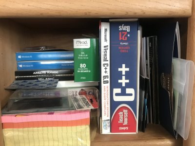
IMG_0703.JPGThis is a Microsoft SAMS series self-learn Visual Basic C++ computer programming course that I bought some 18 yrs ago to self-learn all this myself (I also have a Corel Visual Basic C computer programming course that predates this 1 & have been building my own computers since 2001...) w\ the intention of writing a plunger lift program that would address some of the weaknesses I saw in other PL softwares to improve operations......until I learned that, since I was employed by ConocoPhillips at that time & developing this software using their properties\equipment that I then couldn't patent my own intellectual work & it would all belong to COPC, so I stopped & put all this aside.

So, I come from a place of actual knowledge of what I'm saying here........not just talking points. It's this background that I have is what helps me to see thru a LOT of these mistakes my prior tuner & to some degree others as well have made in tuning when you make tune setting changes that I know are potentially causing code line contentions (breaking code line argument, logic & process) or don't make proper corrections to map settings in the PCM's calibration that will set off unwanted actions that will cause operational issues......just from me studying the OEM tune files & asking questions from sources that I know have this type of background as I know the Ford engineers are inputting settings all based off the PCM calibration's actual code line process mapping & have already solved most of these issues, also knowing that some of this coding is embedded (such as EVAP operations for starters) that HPTuners\SCT, etc doesn't provide\couldn't provide access to except to either enable\disable it, but is coded to work in conjunction w\ the rest......just have to figure it out to then know which settings changes to make\how far to go w\ them to get what you want to happen w\o breaking the rest.......along w\ enough mathematics\sciences background to understand the equations used to then figure out what causes other issues when these equations (such as the tune's ETC TB PTA\EA mapping to rep the actual TB's internal PTA\EA being used for starters as well) are also not followed\used properly. This is VERY HARD to understand\comprehend well w\o a basic computer programming\mathematics\sciences background to help make sense of it all because the majority of what a tuner needs to know is not visually visible thru a tune file......it's what is underneath in the background of any tune file's settings......the operational PCM calibration code line logic process mapping....is what needs to be known.

Very, very few folks actually know\teach all this concerning factory OEM PCM calibrations, regardless of origin for very good reasoning (intellectual property thus copyright laws apply).........even 25 yr+ professional tuners.......w\ PCMs as old as these Spanish Oaks PCMs are.......simply due to the "good enough" mentality that persists in this industry to this day thus some customers are still paying the price for what is essentially tuning complacency......therefore they either don't learn what they needed to learn\should have already learned or don't know what they needed to know\should already know so thus will always come up short......at the time(s) when they don't\can't afford to have that happen.

Why so many like to replace factory OEM PCMs w\ standalone PCMs cause you don't have to contend w\ all the emissions coding......that they didn't want to take the time\effort to learn to then be able to tune around it all to get the HP\TQ they want while at the same time retaining all the emissions functions......even though in reality, the emissions functions are a direct correlation into the actual IC engine's HP\TQ output as BOTH are a direct result of engine efficiency.....efficiency goes up, so does HP\TQ output w\ emissions output improving (decreases) at the same time & when efficiency goes down, so does HP\TQ output w\ emissions output suffering (increases) also at the same time. The only scenario that deviates from this fact is when the engine's max VE output exceeds the cats max exhaust poundage treating capacity......also a known fact in the scientific automotive world for the last 35+ yrs........but not so much in the automotive enthusiast world......why this is so, is beyond me but I have a good hunch that capitalism has a LOT to do w\ it......not a lack of knowledge.

Now you know the other reason why I record\track the Mode 6 Cat CE Ratio results from the PCM (I don't own or have access to a 5-gas exhaust analyzer that most professional tuners will need going forward to stay in business but Ford has already provided 1 for all us DIY'ers if we just stop defeating it & use it)......whatever changes I make in the tune file that ends up showing an improvement in Cat CE Ratio is a dead ringer to also have improved engine HP\TQ output.......not a question of IF, but only HOW MUCH...... Don't need a dyno to know the IF.......only the HOW MUCH.
Example: the Cat CE Ratio results from my last tune revision & DC\WOT run that I've called done was B1 @ .059.....idle LTFT @ -2.3%, B2 @ .086.....idle LTFT @ 0.8% w\ CMBT @ 1,487*F avg....the 1st sets of numbers all show the overall engine combustion efficiency thru the cats operations---cats can only treat what the engine sends into them thru the exhaust, the more efficient the engine combustion is the less HC, CO & NOx they have to scrub out per lb of exhaust gas emitted thus the lower the Cat CE Ratio results will go, perfect 100% result is .000 CE Ratio....this isn't really a measure of the actual cats efficiency, it's actually a measure of the ENGINE'S EFFICIENCY thru the cats ability to use up all of the free O2% the PCM calc'd to send into the cats to treat the amount of HC, CO & NOx in exhaust the PCM also knows was sent into them......the closer the B1\B2 LTFT avg's get to 0% is more proof of increasing combustion efficiency getting closer to true stoichiometry across the entire engine's operational envelope---along w\ the avg operational exhaust temps.....the higher the avg exhaust temps get is proof that more total energy was released thru the engine combustion process thus more available energy to perform more work thus more usable\measurable engine HP\TQ output........it's that simple. If exhaust temps are increasing, the amount of usable energy has also increased thus the amount of TQ thus HP has also increased......if exhaust temps are decreasing, so is the amount of usable energy thus the amount of TQ thus HP has decreased as well. It's up to the tuner to make sure that this exhaust temp increase is coming direct from the engine cyls & NOT from shoddy tuning that has most of this exhaust temp being derived thru the cats having to burn off all the excess HC, CO & NOx from poor cyl combustion efficiency (why most cats are cooked from overheating......so don't use no more OL fueling than necessary to get the HP\TQ out of the engine safely.....it's the EXCESS UNECESSARY fuel used that is causing this to happen, usually due to folks who don't install an efficient enough engine COOLING SYSTEM to help remove enough of this extra heat generated thru the cyl heads thus having to use excess fuel to compensate for it......not good).

Cat CE Ratio results that are rising is a dead indicator of this happening.......

And yes, the butt dyno can easily detect some of the effects from the IF.......

I myself know this as I have a copy in hand of the full automotive scientific catalytic converter study done after OBDII came out in 1996 (before CARB was a thing) that covered all this......up to & including what is needed for any IC engine...including FI-equipped IC engines.....to operate properly using cats & the process of properly sizing them to match\exceed the engine's max VE output under most any operational scenario so all operates properly & legally.

Take this FWIW......just putting this out there for those so interested......................
 
Last edited:

GlassTop09

Senior Member
Joined
May 24, 2019
Posts
1,142
Reaction score
525
Location
Farmington, NM
@GlassTop09 Thank you for your explanations, I would like to understand everything ;)
Sorry for the offtopic question: I have a 4.6 with Bullitt CAI and CMDP, manual.
I found 2 things that differs from all my other cars.

1. A short bucking when shifting 1->2->3. Recorded some data with Xcalibrator and found that the TB closes for 0.1s right when the clutch engage in new gear and the rev drops a bit, despite pedal is still at ~8.

2. A get-off-throttle delay. I have to put a short delay between getting of the throttle and starting to press the clutch, otherwise the revs go up 500rpm. Independent if its WOT or lets say 40% load

Is this fixable?

Thanks!
On item #1......
Question I have for you is........has this engine been tuned? From my reading of your parts lists I'll assume yes.......

Ok, just remember you asked for this...........:)

From my experiences, that bucking is an indicator that your tune may need a little more accel gain transient fuel added to counter the momentary A\F leaning off the sudden inrush of air into engine from initial TB BF movement after a gear shift until the PCM can catch up w\ the A\F calcs to match the airload TQ requested post gear shift & clutch reengagement. There is a switch located at top of clutch pedal that informs the PCM when the clutch pedal is being pressed to decouple engine from drivetrain so it's also looking for the APP pedal to return to full rest so the dashpot throttle control decay rate is used to slowly allow the engine to drop RPMs while the gear shift is being made so the PCM can see the new gear position being selected thus know this gear's drive ratio to use w\ the trans VSS signal off trans output shaft that is derived from the speedo base NV number that entails the rear gear ratio + tire revs\mi so the PCM can calc the mechanical TQ now available to then determine the amount of engine TQ to apply to match the driver requested TQ requests from APP pedal A\D counts now moving off full rest & signal from clutch pedal upper switch telling PCM that the engine has been recoupled to the drive train so it can now use the engine RPM's from CKP sensor to compare to trans VSS MPH signal to make the necessary TQ calcs as the APP pedal is pressed to wherever the driver stops the APP pedal movement causing the ETC to move TB in synch w\ the APP pedal. All this takes the PCM a few secs to go thru but the TB movement is immediate, so this is what transient fueling is set up to provide the necessary extra injector PWM fueling to compensate for until the PCM catches up w\ the MAF airload calcs off the TB TPS% thus A\F control. The new gear ratio is higher meaning LESS mechanical TQ available thus calls for more engine TQ output but if A\F is lean when the engine is initially recoupled to the drive train & put under a load, the engine will start stumbling, by then the PCM airload calcs react causing engine to surge then PCM has to react to this surge by closing the TB causing this bucking cycle until the PCM finally gets this under control thus will smooth out. A sloppy or delayed APP pedal signal spiking output off full rest can aggravate this as well.....but usually some extra transient accel gain fueling will line this out.....even w\ the OEM 55mm TB using the OEM TF accel gain map. Don't need a lot.....a little more here can cure a lot of stuff. Same principle for EFI as a carb using it's accel booster pump\power valve to squirt some extra fuel into primary\secondary BF's when opened\moved. If the APP pedal signal is tested\verified to be good & clean & TB movement is also tested to be good & smooth then the TF IMHO needs to be addressed thru the tune. A lot of folks try to readjust the ETC TB PID control to smooth out the TB swinging.......when it's usually a lack of adequate transient accel gain fueling causing the swinging.....not the ETC TB PID control that is only following the ETC APP throttle control's A\D counts signal sweeps......basic DBW control code logic....the ETC APP is the primary PCM throttle control, the PCM TB TPS is the secondary throttle control that is coded to mimic the ETC APP throttle control signal sweep movements but PCM can divorce the TB TPS control from the ETC APP throttle control as needed in certain circumstances...like cruise control being 1 of them & ETC soft rev limiter being another 1 for a couple of examples (there are more such as Limp Mode which is a PCM engine\driver safety trigger).

This is what I've learned from tuning my own engine......which had a LOT more tuning miscues thrown into the mix but this lack of adequate transient accel gain\TC map fueling was 1 of them......

Auto folks don't have this problem near as often as manual folks will be due to direct clutch coupling\decoupling operations vs a TC....which the auto trans is wholly controlled by the PCM thus it is in control of all this during its shift points. This is usually a by-product of retuning an engine due to any recalibrating of the MAF and\or LWFM tables thus will usually also require a slight readjustment of the transient fuel accel gain map mostly.....the TF accel time constant map usually doesn't need to be touched........unless a larger TB is installed......then both TF accel gain AND TC maps need to be updated to compensate for it. The tuning hack of trying to use the Dynamic Airflow IM volume setting to "adjust" TF IMHO needs to stop.....this setting is what the PCM uses to properly calc ETC predictive airload fueling as it is the simulated inner IM volume after TB that the PCM uses to calc the simulated barometric pressure upstream of the TB along w\ the calc'd simulated IM vacuum pressure in inHg downstream of TB to then calc the SD airmass flow off the TB's tune recorded PTA\EA mapping at the TPS% of TB BF TBA position reported to PCM using the LWFM MAF calibrated airload readings at the same TB TPS% TBA for making proper fuel calcs to add according to the EQ Ratio Lambda fuel control to maintain Lambda 1.0 during CL-Normal Mode or during OL-PE\WOT operations using the OL base fuel Lambda map......so when this setting is not matching the actual IM inner volume post TB, you're throwing the entire system out of alignment thus will get bad ETC predictive A\F calcs which will throw off engine fueling AND cause cats monitoring to be thrown off as well causing potential P0420\P0430 Cat Inefficiency DTC's........have seen\recorded the results both when this is done wrong vs when this is done right.

On item #2.......

Yes, this can be adjusted......is best done thru using a data log of engine operation recording the ETC APP Throttle signal trace along w\ the ETC TB TPS% Throttle signal trace to determine where the adjustments need to be made. There are no in-tune adjustments to correct an APP throttle control signal trace.....the PCM only recalibrates to the APP signal trace it sees at full APP pedal rest position during KOEO thru to start\run then counts the A\D counts from this position off APP signal movement from full rest position to full APP travel & back......so don't rest your foot on the APP pedal when starting your Stang or you can throw this off. Remember that basic DBW throttle control code logic has the PCM ETC TB TPS control mimicking the PCM ETC APP throttle control A\D counts signal generation, so 1st make sure that the APP is operating properly w\o any signal spiking\hesitation (this is usually located in the areas just off APP full rest.......where the vast majority of signal movement thus APP potentiometer wear occurs) before looking any further into the tune side.

During my tuning on my own car, I found that I had to replace my APP assembly........not because it wasn't working but because the signal tracing from it was starting to show inconsistencies that I knew would cause the ETC TB TPS Throttle control to follow suit due to basic DBW code logic programming......which will definately cause engine control anomalies unless it was rectified. The only way that I could see this was thru using HPTuner's VCM Scanner software to graph both throttle control's PID's (but Forscan can do the same thing thru using its Dashboard.....Forscan's PCM PID graphing utility in Oscilliscope Mode).

Once the APP is tested\verified to not be a cause of this issue, then the majority of the time this can be dialed thru readjustment of the dashpot throttle control's decay rate settings (controls the rate of engine RPM decel drop towards engine idle using a min airload decay rate setting per the current dashpot mass lbs\min airflow in use when the APP is released to full rest position) thru the tune file (this is the throttle control coding the PCM uses when the engine RPM's exceed the max RPM's that the PCM adaptive engine idle control coding is used.....usually around 800-900 RPM's as the dashpot's min RPM control is around 1,000 RPM's (why the engine RPM's seem to hang around the 1,000 RPM's mark when decelerating w\ foot off the APP until the car's MPH drops below around 4-5 MPH telling the PCM that the driver's intent is to come to a stop thus go into adaptive idle engine control at which time the engine RPMs will drop down to the desired engine idle RPMs as set in the tune as this is where the PCM will use airload as rough idle control w\ spark timing used as fine idle control to maintain the desired engine idle RPMs.

Note that I didn't say "fixed" or "fixable"...............

I know the temptation to compare different OEM manuf's PCM operational throttle control coding thinking that they all operate\should operate in the exact same way\manner........but the reality is that due to intellectual property thus copyright laws concerning infringement of this said intellectual property concerns.....no OEM's ETC throttle control will operate exactly identically from 1 OEM manuf to another....even if both are using the same type of engine control technology thus there will be slight differences between their operations to not infringe on each other's intellectual property rights using the same base technologies under US Federal & international trade law.

Just saying...................sometimes you just have to make the mental readjustment between driving a manual Toyota vs a manual Ford S197 as only so much can be done to try to make them operate identically.......when they're specifically coded to NOT be "identical" but "similar".

This the type of stuff that I get a kick out of learning as I find it very useful at times.........

Hope all this helps you out...............

:beer:
 

GriffX

Member
Joined
Sep 28, 2017
Posts
525
Reaction score
177
:hail: Thank you!
It will take some time to understand all.... I have a XCalibrator with Livelink for logging. I hope I can test the APP only with ignition on (car is in winter storage). I tried to do some programming several years ago on my supercharged Mercedes with ugly Siemens ECU and was not able to find a definition file for the bin file.
I bought a Xcalibrator from Bamachips before American Muscle owned it. I'm in Germany, was not easy to get one. This bucking started with a tune for the charge-motion valve delete (would like to have camshafts, long tube headers are not allowed in Germany). With the last revision it seems to be almost fixed, I want to understand what's going on, because I'm not sure that my car does not have a problem (worn clutch, dragging brakes, electronics). I have seen spikes in the pedal position PID sometimes, will test it.

Driveability of newer manual transmission cars has become awful. Especially Audi or VW have erratic pedal behavior for me.

I once got into the rev limiter, it was like hitting a wall. Don't think that such a fuel cut (?) is healthy for the car.
Again, Thank you!

PS: Recorded the APP, there are some spikes, not sure if this is relevant. But, I noticed that I cannot press the pedal smooth, only in steps
pedl.png
 
Last edited:

GlassTop09

Senior Member
Joined
May 24, 2019
Posts
1,142
Reaction score
525
Location
Farmington, NM
This bucking started with a tune for the charge-motion valve delete (would like to have camshafts, long tube headers are not allowed in Germany).
Ok, here is another item\clue that is validating the need for extra transient accel gain fueling. CMCV's are essentially an airflow restrictor control (thus a "secondary throttle airflow control" system) that is operating under the engine's main throttle airflow control, when they are in the normal position (closed) so all the OEM transient fueling for accel\decel is tuned w\ these CMCV's in place (yes they create airflow port velocity into the intake port using friction thus a pressure drop from airmass volume flow across a smaller cross-section of a shorter intake runner's open area to simulate the same intake port airflow velocity of a longer intake runner that is created by the same frictional forces created from the drag of airmass flowing in contact w\ the inner intake runner walls across the longer flow path decreasing the inner airflow area from shear--airmass that is now rolling across the inner intake tract walls instead of laminate flow--for smooth air flow causing this smooth airmass flow to accelerate....but in both cases are actually restricting the overall total airmass volume that will enter the intake port at the same engine low RPM. The difference between the 2 is that the longer intake runner design will still deliver more overall total airmass volume into cyls thus make more low end TQ output vs this CMCV\shorter intake runner design due to less overall laminate airflow disturbance......FYI. This is Ford engineers chosen method of trying to correct a shorter IM runner design for higher RPM HP\TQ output to provide more usable low-end HP\TQ output for daily normal driving AND improved MPG AND improved emissions.
The entire purpose of using CMCV's is to create extra air tumble\swirl into intake ports to enhance air\fuel atomization\mixing to enhance more efficient combustion........which is what increases engine TQ output & improves emissions. Remember EFI port fuel injection by design is injecting fuel into airmass stream at the END of the IM's intake runner tract at the back of the intake valves at the time the intake valves are starting to open thus has very little time for air\fuel to atomize naturally into the full airmass flow going into the cylinders, as opposed to a carb that is adding fuel to airmass before it even enters the intake manifold, thus has a lot of time for fuel to completely atomize into the airmass sitting in the intake manifold plenum\intake runners before it enters the intake ports in cyl heads when the intake valves open.

If you look at the OEM TF accel\TC maps, you'll note around the 2,500 RPM row a step divergence in the settings that show a significant increase in TF being called for........that step is representing the changeover point from CMCV closed to CMCV open........where the airmass volume flow into the intake ports is increasing from these CMCV plates being opened along w\ increasing engine RPM's thus not restricting the airmass volume entry anymore, thus the Ford engineers had to add more TF gain fueling to compensate for this when the ETC TB TPS throttle control cycles the TB BF's when the CMCV's are open........

When these CMCV's are removed, you're actually increasing the total airmass volume flow into the cyls now vs prior, but if the TF accel gain mapping isn't adjusted to compensate for this extra airmass, the engine will be momentarily leaned out every time the ETC TB TPS throttle control moves the TB BF's causing momentary loss of engine TQ (that gets blamed on the CMCV removal.....which is true due to their removal causing an INCREASE of airmass volume into cyls that isn't accounted for w\ the necessary fueling) when put back under load causing the bucking until the PCM catches up w\ corrected A\F mix once the MAF starts to generate corrected airload off TB TPS% for corrected fueling to be applied.

This fact is overlooked\missed by a lot of folks w\ this 3V & is misdiagnosed as ETC TB TPS PID control issues........when it really isn't.......it's a simple A\F mix\atomization issue.

Get this TF corrected & you'll find out from your engine's low speed TQ output going up making off idle accel much more crisp, snappy thus responsive since the engine won't be being momentarily leaned out going forward. The 1 disadvantage from this will be a potential drop in MPG as you WILL be using more fuel overall but as I said prior, if corrected properly.....meaning adding only enough extra fuel to match the extra airmass volume to correct to Lambda 1.0 instead of being ham-handed w\ the additional added fueling......the MPG loss can be minimized AND you will also be able to retain the emissions output.

I would suggest adding this across the entire TF accel gain map as Ford has already initially set it up in 5% increments until you get the results you're looking for. A WB O2 sensor will help out in doing this accurately but can be done using the NB O2 sensor STFT outputs as well while in CL.

So, in the end, what Brent White @ Brendspeed is saying about these engines not losing low end TQ output from CMCV removal is true.........if the proper tuning corrections are applied when the CMCV's are removed to correct the A\F mix thru proper TF accel gain\TC map adjustment along w\ a little TQ Management Driver TQ Request mapping massaging from the 16 thru 92 A\D count rows for any extra spicing desired...........

Also, since we're talking this stuff here, you might want to look at the tune's fuel injector reference crank angle setting (this is the EFI port injection system's EOIT--end of injector timing--point where it will stop injecting fuel based off the crank angle degrees of a camshaft's adv dur IVO point.....just subtract the camshaft adv due IVO degrees from 360* to get the CA equivalent) & make sure that this setting matches any camshaft's GI adv dur IVO point at the camshaft 0* VCT reference w\ these 3V's. The entire purpose of this is to also enhance A\F mix atomization off the back side of hot intake valves along w\ the swirl action of the A\F mix entering cyls from initially opening intake valves created from exhaust scavaging\piston downward movement during the intake stroke AND so PCM can maintain this fuel injection EOIT reference relationship during VCT operations when it is swinging the cam timing back & forth.

OEM cams adv dur IVO is 15* BTDC or 345* CA reference..... This can be fine adjusted to get the best atomization\swirl action possible (which is the MAIN area for optimizing this w\ port EFI). I find that adding 5* to the correct CA ref setting makes a very noticeable improvement in low speed TQ output w\ my 3V. You don't want to get crazy here as you'll end up having raw fuel being sprayed somewhat directly into CC thru open intake valves losing some atomization efficiency, so be advised.

PS edit---During my tuning of my own engine, I found that my prior tuner didn't correct this inj CA ref to match my Lunati VooDoo cams adv dur IVO point---left it set at 349.5* CA....4.5* advanced off the OEM cam's 345* CA ref....when my Lunati cams adv dur IVO was 30* BTDC or 330* CA---thus a full 19.5* advanced so my injectors were firing thru well opened intake valves spraying raw fuel into cylinders during the intake stroke w\o the full benefit of atomization\swirl......along w\ all TF accel\decel gain\TC fueling still set to match the OEM 55mm TB's PTA\EA sizing w\ CMCV usage when I had a BBK #1763 62mm TB\currently a FP 62mm TB installed which has a MUCH larger PTA\EA sizing, which was causing a MASSIVE A\F leaning out on every ETC TB TPS% BF movement on top of it all as I also had\currently have my CMCV's removed causing all kinds of operational issues across the entire engine operational range. So, when I say that I got a noticeable low speed TQ output increase from me rectifying all this mentioned, I didn't need a dyno sheet to know it as you could definitely FEEL it.

I've witnessed a LOT of tuning folks.......even long tenured professional tuning folks......on the HPTuners Ford forums absolutely mess this up when aftermarket camshafts are installed by not correcting this setting to match up to the new cam's adv dur IVO CA point (most just leave the 345* CA setting for the OEM cams in place, throwing the Ford EFI fuel injector EOIT to camshaft IVO timing off). Ford used .006" advertised duration cam timing points to adjust\set VCT cam timing......not .050" lift cam timing points so you really need to correct your cam card's .050" lift duration cam timing to .006" lift advertised duration cam timing points or you'll have injectors firing thru intake valves opened .044" off their valve seats.......

I'm mentioning this since your car has been tuned to check this for proper application......

Hope this helps...............

PS edit--You can test the APP during KOEO w\ your datalogging software as well.......just have it recording during KOEO & cycle the APP after giving the PCM a sec or 2 to perform it's calibrations w\ APP at full rest.
 
Last edited:

GriffX

Member
Joined
Sep 28, 2017
Posts
525
Reaction score
177
That was very helpful! When I removed the CMCV, look inside reminds me of the Honda Fireblade, 2V in low rpm and switching to 4V. I think it is also a reason that these Ford engines don't need secondary air injection systems for emission reduction ?
I have taken a look at HP TUners they are 500€+, don't understand the credit system, is it bound to the VIN? Unfortunately it does not read my old Mercedes Siemens SIM4LE.
I guess the tuner comes with a pre defined definition file for the ECU, Spanish Oak?

I'm in doubt that I will fix all issues with mail-in-tunes only. Will take out the APP next days and inspect why it is hard to press down.
You helped me a lot!
 

GlassTop09

Senior Member
Joined
May 24, 2019
Posts
1,142
Reaction score
525
Location
Farmington, NM
That was very helpful! When I removed the CMCV, look inside reminds me of the Honda Fireblade, 2V in low rpm and switching to 4V. I think it is also a reason that these Ford engines don't need secondary air injection systems for emission reduction ?
I have taken a look at HP TUners they are 500€+, don't understand the credit system, is it bound to the VIN? Unfortunately it does not read my old Mercedes Siemens SIM4LE.
I guess the tuner comes with a pre defined definition file for the ECU, Spanish Oak?

I'm in doubt that I will fix all issues with mail-in-tunes only. Will take out the APP next days and inspect why it is hard to press down.
You helped me a lot!
On the HPTuners credit system application\usage:
Universal Credits – HP Tuners
Really can't see\understand why this is so misunderstood...........this answers every question you've asked here concerning HPTuners credit system\usage.....

Yes, in order to properly correct\fix most anything tune-wise, it's much better to get w\ an actual tuner who can offer remote tuning like Lito, an actual local tuner using a dyno.......or DIY using your own tuning software\interface system.
 

GlassTop09

Senior Member
Joined
May 24, 2019
Posts
1,142
Reaction score
525
Location
Farmington, NM
FYI...........................

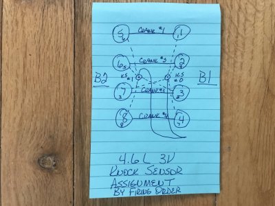
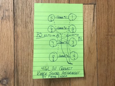
I've been going back thru my work & I might have solved the riddle concerning my #2, #3 & #5 knock pattern while the rest are clean........it appears to be a KS mic assignment mistake in the OEM tune files that the Ford engineers missed between #2 & #6 cyls.

To help all see this, I'm reposting this picture I had posted in this thread prior (follow the dotted lines):
Ford 4.6L Knock Sensor to Cylinder Assignment by Firing Order.JPGThis reps the existing in-tune knock sensor mic to cyl assignment in all OEM SO PCM calibrations. The intended KS mic to cyl pattern is for any following cyl in firing order to use the opposite KS mic from the leading cyl to prevent excessive KS mic noise influence, you will find this to be true for all cyls.......except for #7 to #2 cyls & #6 to #5 cyls.......they are using the same KS mic which is out of pattern from the rest of the cyls (follow the dotted lines I drew from each cyl to the KS mic they are assigned to). So, IMHO the #2 & #5 cyls are suffering from excessive KS mic noise influence from their leading cyls in engine firing order since they are using the same KS mic! The rest of the cyls in firing order don't have this issue as they are using the opposite KS mic from their leading cyl in engine firing order, so #3 cyl's knock was most likely the real cyl knock since it is using the opposite KS mic from #1 cyl while #2 & #5 cyls knock is being aggravated by the leading cyl (#7 cyl to #2 cyl & #6 cyl to #5 cyl) in the firing order since they're using the same KS mic.

So, to correct this I reassigned #2 cyl from #0 KS mic to #1 KS mic & #6 cyl from #1 KS mic to #0 KS mic in my next tune revision.........now the entire engine cyl to KS mic assignment will be corrected so all following cyls in engine firing order will now be using the opposite KS mic from the leading cyls as follows in this picture (follow the dotted lines):
Corrected Ford 4.6L Knock Sensor to Cylinder Assignment by Firing Order.JPGThis now shows a fully corrected cyl to KS mic assignment pattern across the engine according to engine's firing order so no leading\following cyl pairing will be using the same KS mic going forward.........which I believe was the intention of the Ford engineers to use in all of the SO PCM calibrations but wasn't caught during QA\QC checks.......which I also believe is the main issue behind Per Cyl Mode being perceived as flawed, but this will also affect Global Mode operations as well but Global Mode will wash some of this out due to the up\down constant averaging algorithms in addition to the Window Length\Window Offset settings being applied to then show all engine knock as a single output repping all 8 cyls.....whereas in Per Cyl Mode I believe this up\down constant averaging algorithms isn't being used thus is only using the Window Length\Window Offset settings alone for each cyl after a single cyl's noise pattern exceeds its sensitivity threshold map settings when it is fired during compression stroke\power stroke from another noise signal generated from somewhere else that "collides" w\ the initial noise created in synch w\ the spark plug firing\igniting timing thus driving the cyl noise above the cyl's sensitivity threshold map tuning that reps the noise "floor" of the firing cyl.

Gonna test this out today to see if all the current known cyl knock goes away from just a simple cyl to KS mic reassignment of #2 cyl & #6 cyl so all cyls now are following the same KS mic assignment pattern during the engine firing order sequence across the board using the Ford OEM tuned per cyl knock sensitivity threshold map settings.

I was seeing this all along but never made the "connection" until this morning...........

If this is successful, this will open all up to further increase WOT spark timing thus potentially increase max engine HP\TQ output further using Per Cyl Mode knock control.

PS edit--Even if this works & clears all cyl knock that I've currently seen, I'm going to keep my total WOT spark timing set @ 28* max where it is currently since I also revisited my prior tuner's tune I datalogged that I saw where he had tricked the PCM to go into OL during WOT thru having the PCM think the engine was still cold which disabled the KS's during WOT..........but I now noticed that this also disabled the VCT which parked the cams at 0* retard thus full advanced during WOT w\ spark timing actually running at 27* max (followed the base BKT spark advance map settings).......so if I put my car on a dyno now w\ all working correctly w\ WOT settings in currently, my engine should already make more max HP\TQ than it did then.....especially w\ VCT actually retarding cams some 18*-20* instead of 0* during WOT.
 
Last edited:

GlassTop09

Senior Member
Joined
May 24, 2019
Posts
1,142
Reaction score
525
Location
Farmington, NM
FYI........................

Flashed in new tune revision Per Cyl Mode #6 (only in-tune correction made was KS mic to Cyl reassignment as diagrammed in post #415) today & made DC\WOT run. Checked datalog & the results clearly show definate progress in right direction. To show all this I'm gonna start w\ the last WOT run from data log on 2-7-23:
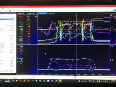
WOT Run Per Cyl Mode New TF Accel Gain TC Map Settings FP 62mm TB 28 Degrees Max Timing 2-7-23.JPGThis is the 2nd picture I put in post #406 where I had made the new TF accel gain\TC map changes using the 2.32 & 1.48 multi's I got from calc's to correct the OEM TF accel gain\TC mapping for the OEM 55mm TB to fit my FP 62mm TB. In this tune revision Per Cyl Mode #3, I had the WOT OL Lambda fueling set @ .82 which w\ the new TF accel gain\TC mapping, arrested #5 cyl knock but not #2 cyl knock & #3 cyl knock came back....even though when using WOT OL Lambda .84 fueling #3 cyl was clean w\ no knock while #2 cyl showed knock in both pictures at both 17.5* & 28* WOT max spark advance timing.

Please make note of both KS #1\#2 mic voltage output graphs & remember to reference back to them going forward.

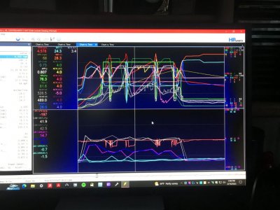
Now here's a picture of WOT run dated 2-18-23 from tune revision Per Cyl Mode #4 (only in-tune change was resetting WOT OL fueling from Lambda .82 back to Lambda .84......made this change to see if #5 cyl would stay clean & not knock from new TF accel gain\TC mapping):
WOT Run 2-18-23 With OEM KS to Cyl Assignment and WOT Fueling .84 Lambda.JPGYou can plainly see on data log #58 that from leaning out the WOT OL Lambda fueling from .82 to .84 caused #5 cyl to start back knocking along w\ #2 cyl but #3 cyl went clean again when I leaned out the WOT OL fueling back to Lambda .84 (where it showed to be clean in prior WOT run in 1st picture in post #406 ran on 2-7-23 using 17.5* max WOT spark advance timing). Note in this 2nd picture that both KS #1\#2 mic voltage graph lines are running in identical pattern to the 1st picture.......... After this run was made I had resigned to reset the WOT OL Lambda fueling back to .82 in revision Per Cyl Mode #5 & had flashed it in on same day, was in process of performing the DC & was gonna make a WOT run on it but a vehicle showed up out of nowhere & got in the way just as I was about to nail the APP, so I aborted the WOT run, finished the DC (datalog #59) & shut it all down for the day............until this morning when the thought hit me concerning the in-tune KS mic to cyl assignment relating to my #2, #3 & #5 cyl knock issue.

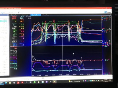
So, I pulled up my copy of Per Cyl Mode #4 tune revision (matches the 2nd picture data logged WOT run), made the in-tune KS mic to Cyl assignment change as mentioned\diagrammed in post #415 (only change made in tune file), saved it as Per Cyl Mode #6 revision & flashed it in PCM then performed DC\WOT run today as follows:
WOT Run 2-19-23 With Corrected KS to Cyl Assignment and WOT Fueling .84 Lambda.JPGWell it looks like we're getting somewhere w\ this setting change as well on datalog #60.......note car is using the same tank of E10 91 oct fuel (got snowed out right after the 2-7-23 runs so have been shut down until 2-18-23 waiting on snow to melt off\roads to dry off). Note that #2 cyl knock has now fully disappeared & is clean & #3 cyl knock has not reappeared so #5 cyl is now the only cyl showing knock.....but note that the overall severity of #5 cyl knock has diminished in this picture vs the 2nd picture AND both KS #1\#2 mic voltage graph lines have changed pattern vs the 1st\2nd WOT run pictures.......all from just a reassignment of #2 cyl from #0 KS mic to #1 KS mic & #6 cyl from #1 KS mic to #0 KS mic to correct the entire KS mic to Cyl assignment so all leading cylinders in firing order sequence are using a different KS mic than all following cylinders in firing order sequence.......nothing else. The KS mic voltage graph lines across this entire data log have also changed.......gotten a LOT cleaner & have stopped the odd, random voltage signal down spiking so this was also being caused by the KS mics getting loaded up w\ excessive cyl noise from #7 cyl to #2 cyl as well as #6 cyl to #5 cyl using the same KS mics in successive 90* cyl firing sequencing instead of using the opposite side KS mic.......like all the rest were doing except these 4 cyls......but they are now.

Please make note also that this same per cyl to KS mic assignment issue is adversely affecting the Global Mode knock control operations as well if it is not corrected.....but since this Global Mode knock control is averaging all the same per cyl knock detected to come up w\ an avg cyl knock across all 8 cyls, this mode is in essence masking this mistake by the Ford engineers thus is falsely cutting engine HP\TQ output as well as is perceived\blamed on the Per Cyl Mode knock control in this SO PCM's OEM calibrations by a LOT of tuners. I gotta wonder just how many of these tuners have actually looked at\figured out this simple cyl to KS mic assignment error that Ford made in all 05-10 OEM SO PCM GT calibrations (yes, I've checked them all & verified that ALL of them are incorrect) that I would've most likely have missed as well......if I had given up on using the Per Cyl Mode knock control (which helped expose this Ford created KS mic to cyl mapping error) & accepted the Global Mode knock control as "good enough" as it was originally set up in all 05-10 SO PCM GT calibrations......which we now know is also giving faulty cyl knock info from the same Ford created error that was causing the Per Cyl Mode knock control to do the same thing.

So now this riddle of #2, #3 & #5 cyls only showing cyl knock has been resolved so now the only cyl that had any real cyl knock from light detonation to begin with was #5 cyl alone........the rest was "manufactured"..........

Ok now back to the issue w\ #5 cyl knock..........note that the origin of all #5 cyl knock is starting during the KS applied spark advance timing ramp up during WOT run right after ETC APP\TB TPS signal cycling during WOT gear shifts 2nd to 3rd & 3rd to 4th......right in the area where the PCM is applying TF accel gain\TC fueling to offset the WOT OL to CL back to WOT OL fuel switching saga, so it appears that we're still a little short here so in next tune revision Per Cyl Mode #7, I've added 10% more TF accel gain map fueling from 3,500 RPM & up rows to try to arrest this, but also note during the 4th gear WOT pull, the #5 cyl knock got worse as the pull went along......I think this is gonna have to be finally resolved in the end by resetting the WOT OL fueling back to Lambda .82......but by God I'm gonna force this engine to PROVE that this has to happen......for just 1 cyl out of 8......to keep from over fueling the rest just for 1 cyl. So far, the fuel pump graph data is showing that the fuel system can easily deliver the extra needed fuel in both cases so I'm gonna hit the TF accel gain map's 3,500 RPM & up row settings (only 2 rows) very hard over the next few days based on WOT run results to see if I can stabilize #5 cylinder w\o having to increase the OL base fuel Lambda map settings from .84 Lambda as this fuel setting showed to be the best for engine WOT combustion stability using the Mode 6 MM last cyl counts data to check for this.

But during the initial 1st gear WOT hit I did noticed the MIL light started flashing momentarily (not the 1st time I've noticed this since swapping in the Brisk Silver XOR14YS plugs.....were gapped at .030" when 1st seeing this occur......now gapped at .040") indicating cyl misfiring under a heavy load causing cat damage then cleared up after the 1-2 shift, but all subsequent Mode 6 MM data recorded showed no cyl misfires (all 0.0%) & hardly any A\B misfires (less than .07% for Type B & 0.0% for Type A), so from this data I might be ordering a new set of NGK Iridium IX ZNAR6AIX-11\0372 fine-wire OEM spec plugs soon in near future to replace the Brisk XOR14YS plugs currently installed as I've never saw\recorded any of this before replacing them w\ these Brisk plugs.

So, this 4.6L of mine may need the extra heat range in the OEM spec'd plug tips to burn cleanly & stable under high engine loads.........will be very interesting to see all this clear up......even the #5 cyl knock.......from a plug change back to OEM heat range specs!

This is where I'm currently at w\ tuning this engine of mine..........we're getting closer to finishing & continue to find & resolve tune related issues that I'm sure a LOT of folks have missed over the years.

Every time I think I'm done I keep finding\running into tune-related issues that need resolving beforehand. I've also ran all this by Jeffery Evans @ Evans Performance Academy to see what he has to say about this finding as well........

Making progress........slowly but surely.

PS edit (2-20-23)--Just thought before I go to bed, that the few tuners who have a Plex or TunerNerd Pro knock detector to use while on a dyno to actually piggyback off the existing engine knock sensor mics (best scenario) or install a separate knock sensor on engine block under the IM in close enough proximity to the existing knock sensors location to then actually find the real per cyl knock sensitivity threshold levels to then reset the in-tune per cyl knock sensitivity threshold map settings correctly will have a distinct advantage over a remote tuner who will have to roll w\ what the datalogs tell them......unless they've been here, figured this out & made the necessary changes in the KS mic to cyl assignment map to fix Global Mode properly since I know the vast majority of them are using Global Mode knock retard control.......which will still hide some cyl knock by averaging it out across the rest of the cylinders.
 
Last edited:

GlassTop09

Senior Member
Joined
May 24, 2019
Posts
1,142
Reaction score
525
Location
Farmington, NM
FYI............................

Ok folks, I've finished cracking the code on all this going forward so the end is now in very plain sight.

After post #416 in AM @ 2-20-23, I went thru tune revision Per Cyl Mode #6 & Datalog #60 w\ a fine tooth comb after getting up out of bed & started looking for any clues to try to find the culprit for #5 cyl knock (since resolving the rest of the weird cyl knock on #2\#3 cyls by a simple KS mic reassignment to #2 cyl & #6 cyl as laid out in previous post that also removed the undue noise influence from #5 cyl so I know what's left is real knock), but since I knew that I had reset the WOT OL base fuel map from Lambda .82 to Lambda .84 in Per Cyl Mode #6 revision (that I had set in Per Cyl Mode #3 revision that showed to work in clearing #5 cyl knock in Datalog #57 due to this cyl having a tendency to run leaner than the rest due to it's IM runner position being ahead of the IM plenum & 1st in line w\ the EVAP pitot tube behind TB flange), I reset this map back in Per Cyl #7 revision to Per Cyl Mode #3's OL base fuel map (only change made), flashed it in & made DC\WOT run as follows:
WOT Run 2-20-23 Correct KS Cyl Assign OL Lambda .82.JPGAs you can now see, this OL base fuel map change didn't work this time & I couldn't figure out why\what changed as I had all fueling.....including TF accel gain\TC mapping......still set up same as was set up in the Per Cyl Mode #3 revision that showed to arrest this issue w\ #5 cyl, so I figured that something else that involved fueling has to be influencing this so I dug thru all datalogs #57, #58, #59, #60 & #61 the rest of the day to see what was going on..........found out that the fuel pump output had slightly dropped off even though I haven't messed w\ any of this since the beginning. Got to checking back thru all tune Per Cyl Mode #3, #4, #5, #6 & #7 revisions.....all fueling was set up identical so went back thru the datalogs then got a thought to revisit the WOT ETC APP\TB TPS signal cycling during gear shifts & found that thru this cycling, the fuel pump was being delayed to ramp back up when engine was reengaged after 2-3 & 3-4 gear shift somehow causing engine to go momentarily lean enough to start #5 cyl to knock during the PCM applied KS spark advance timing ramp so FP was actually late w\ TF accel gain\TC fueling as well as the OL base fuel map Lambda fueling (w\o a WB installed you can't easily see this.....I finally caught it thru looking closely at the inj DC vs commanded FP DC vs inj PWM graphs in all datalogs making note of the inj DC vs inj PWM variations across the datalogs) so this has been going on for quite some time. I also made note by using the VCM Scanner's cursor line when lined up on the ETC APP A\D counts graph line at the 545 counts point (where the PCM will end WOT transition & go into full WOT OL-PE) that the ETC TB TPS signal wasn't nowhere close (was at 34.7%) to the 42% setting I had input in the OL Fuel TPS Thresh map (this map sets the threshold to instruct PCM to switch into OL fueling off the OL base fuel Lambda map & disable the NB O2 sensors) so this process was actually being slightly delayed which will also slow\delay the PCM calling for fuel pump to ramp up.

So, since I had some real data to use, I went into Per Cyl Mode #8 tune revision this morning & reset all this so the actual signal offset between the ETC APP throttle control being much faster than the ETC TB TPS throttle control in actual operation is captured (reset the OL Fuel TPS Threshold settings from 42% to 35%), then went into the ETC control tab & lowered the APP throttle control's WOT Disable setting from 455 to 350 (to slow down the switching from WOT OL back into CL as much as I could)......at this 350 A\D counts setting (34% TPS), the ETC APP under all CL-NM driving would not cross 350 A\D counts unless doing 5th gear lugging up steep inclines, so a good place to leave this (so even if TB TPS actually exceeds the 35% setting in OL Fuel TPS Threshold map during a 5th gear incline lug, the PCM will not go into WOT OL-PE since the ETC APP throttle control hasn't 1. released the PCM to even consider WOT since APP counts are still below 350 AND would also 2. still be below the APP Pedal Pos Wot Start 456 setting that actually tells PCM to start blending into WOT if for some reason the ETC APP throttle control did exceed the 350 WOT Disable setting but not exceed the Pedal Pos WOT Start setting) then left all the rest as was set in Per Cyl Mode #7 revision, flashed it in & made DC\WOT run as follows:
WOT Run 2-21-23 OL Lambda .82 Readjust ETC APP TB TPS to Get Into WOT OL Fueling Quicker.JPGNow we're cooking! This revision almost cleared all this up w\ #5 cyl knock so I've gone into Per Cyl Mode revision #9 & optimized this as much as I could (reset the OL Fuel TPS Threshold setting from 35% to 32% to ride the ETC APP throttle control 545 A\D counts signal as tight as I can w\o breaking the EVAP side of this) & went into ETC tab & started lowering the APP Pedal Pos WOT Start setting from 456 A\D counts (44% TPS) to 430 A\D counts (42% TPS) to start WOT initializing quicker, left all else as set & saved file for flashing in AM.

Just to show once again the effect these settings changes in tune revision Per Cyl Mode #8 that improved the WOT operations have on emissions, this is the Mode 6 Cat CE Ratio results recorded after this same 2-21-23 DC\WOT run:
B1 @ .020......idle LTFT @ -3.1%
B2 @ .031......idle LTFT @ 0.8%
CMBT @ 1,492.5*F avg (refer back to post #409 where I posted concerning the role engine efficiency plays w\ HP\TQ & emissions.......)......a new all-time best emissions result out of these MF #5461336 CARB-cert TWC aftermarket cats thus also increased peak HP\TQ output from this old high mileaged NA 4.6L V8.

After finishing\saving latest tune revision, I went back into the Jeff Evans 05-10 Ford Mod Motor HPTuners training videos & rehashed his video on Fuel Pump Setup\Control & from this video I realized that some of my issues stem from all the resetting\tuning I've done to\for this FP 62mm TB which is calling on SO PCM adaptive fuel pump control to adapt the Ford tuned OEM base fuel pump desired voltage map settings based off the OEM 55mm TB (PCM will save all fuel pump voltages it changes from the base fuel pump desired voltage map in tune file in KAM that PCM makes correcting this base map settings itself to the new fueling demands made due to this FP 62mm TB......but is lost on every tune revision flashed in PCM since reflashing clears the KAM.......thus PCM has to start over making all these corrections off the same base fuel pump desired map settings Ford tuned in conjunction w\ the OEM 55mm TB), so I checked my master Per Cyl Mode channel file for the necessary channels needed to use in the Fuel Pump Volts histogram (had all loaded except the fuel pump actual volts channel......is now loaded\saved in master Per Cyl Mode channel file) so that when I flash this last revision in & make DC\WOT run, I'll be recording all the necessary data in datalog to then run it all thru this histogram to capture the PCM KAM corrected\stored desired fuel pump voltage data from running this FP 62mm TB to use to update the in-tune base fuel pump desired voltage map data so I won't be losing it going forward......this will also go a long way to help resolve the WOT fuel leaning issue since the learned KAM data will now become the base tune fuel pump desired voltage map data.

So, this next DC\WOT run is gonna be a very long one in order to capture as much of this PCM corrected KAM data as possible in this datalog, then I can replay the log back at home w\ the histogram datalog layout loaded up to process the captured data to then copy it all into the next tune revision's base fuel pump desired voltage map to update it before flashing it in PCM.

Sometimes you just gotta keep chopping on that tree to eventually fell it......even when using a hatchet instead of an axe\chainsaw.......as persistence will pay out in the end...........if you just keep chopping away at it long enough..........

This was the last hurdle to solve that was keeping me from finishing this tuning.......
 
Last edited:

GlassTop09

Senior Member
Joined
May 24, 2019
Posts
1,142
Reaction score
525
Location
Farmington, NM
FYI..........................

Here's shots of engine's calculated VE% performance during the WOT run 2-21-23 while in 2nd, 3rd & 4th gears:
WOT Run 2-21-23 2nd Gear 4.6L SBE Lunati Cams VE Output.JPG WOT Run 2-21-23 3rd Gear 4.6L SBE Lunati Cams VE Output.JPG WOT Run 2-21-23 4th Gear 4.6L SBE Lunati Cams VE Output.JPGMind you, all this is w\ MF #5461336 CARB-cert TWC aftermarket cats installed in Kooks X-Pipe exhaust that are testing out to be at near 100% catalyst efficiency...............engine VE% output is also showing to have increased to go w\ what was said prior concerning overall engine efficiency relationship correlating w\ emissions & HP\TQ output...........looks to be breathing very well\exhaust very free flowing to me.

All from a well-worn ole NA 4.6L 3V SBE V8 w\ 164,572+ mi currently on the clock...........

Posted for informational purposes.
 

GlassTop09

Senior Member
Joined
May 24, 2019
Posts
1,142
Reaction score
525
Location
Farmington, NM
FYI........................

Got tune revision Per Cyl Mode #9 (reset ETC APP Pedal Pos WOT Start setting from 456 A\D counts--44% TPS--to 410 A\D counts--40% TPS--to take this to absolute lowest setting that should stay above the ETC APP throttle A\D counts signal during CL-NM to get PCM to start blending into WOT quicker & reset OL Fuel TPS Threshold setting from 35% to 34% to match up as tight as possible to the ETC APP throttle Pedal Pos WOT End setting of 545 A\D counts--53% TPS--w\o breaking synch w\ ETC APP throttle so EVAP continues to shut down w\ the NB O2 sensor disablement......all else left as set in prior revision) flashed in this afternoon & made DC\WOT run as follows:
WOT Run 2-22-23 ETC APP WOT 350-410 & OL Fuel TPS Threshold 34%.JPGSuccess!!! We got #5 cyl to stop knocking & clean up on a 1\4 mi simulated WOT run so there's nothing else left to do\look at..........she's a done deal! Note during 4th gear pull #2 & #3 cyls made a very brief appearance but was gone quickly so I'm not gonna sweat over that at all.

While going thru the rest of the DC (which included some extended hiway driving in addition to my usual route to record as much fuel pump voltage data as possible to update the in-tune FP desired voltage to fuel flow map) I got the itch to make a 4th gear, 2,500 RPM to limiter WOT "dyno" hit, so once I got into a good stretch of hiway on US 550 S that had no vehicles in front of me, I slowed down until engine tach showed 2,500 RPM's, shifted into 4th gear & as soon as the RPMs hit 2,500 RPM's I nailed her........engine just responded w\o a hitch & she wound up very nicely & very fast pulling smoothly & strong (I was watching the tach.....) & when I saw her cross 6,000 RPM's\120 MPH I knew she was gonna pull all the way to the limiter w\o let up.......just as I thought that thought, my OEM Ford hood bug shield's plastic mounting clips couldn't handle the wind sheer drag forces across the shield anymore & they pulled out of the mounting brackets & sent my bug shield flying over the top of the car so I immediately let up as I was sure that the hood was gonna be next.....but she held in there so I just kept on going as I was pretty sure that the shield was destroyed (had it on car since 1-2018) & finished the rest of the extended DC & got back home. Checked the front of car......all else was good......bug shield never made contact w\ car & all mounting clips\rubber bumpers were still on hood & undamaged, so I ordered 2 more of these (Ford part# 5R3Z-16C900-AA) from CJ Pony Parts to replace 1 & have a spare on hand as these parts are gonna be getting very scarce soon.....this time she's getting bolted on using some black anodized M6 license plate mounting bolts w\ flat & lock washers & blue Loctited nuts so won't have this happen going forward. Anyway, here's this run:
WOT Run 2-22-23 4th Gear 2,500 RPM to Limiter.JPGWOT Run 2-22-23 4th Gear 2,500 RPM to Limiter VE Output (1).JPG
WOT Run 2-22-23 4th Gear 2,500 RPM to Limiter VE Output (2).JPGYou can see that #5 cyl started knocking for a spell then cleared up & was all good the rest of the pull so there must've been something in cyl like a piece of carbon on top of piston causing a hot spot under heavy load that finally got dislodged & blown out exhaust as you can see in the KS mic traces a substantial change in #1 KS mic voltage signal pattern where the #5 cyl knock stopped & cleared out..... You can also see that she wasn't letting up until I let up (RPMs were steadily climbing along w\ MPH) at 6,230 RPMs (where the TB started closing off ETC APP throttle signal drop) but at 6,142 RPMs she crested at 84% VE max & by 6,194 RPMs was beginning to flatten out\drop off MAF lbs\min airload just before I let up. ECT was at a very good 201*F w\ IAT @ 25*F so she was breathing a lot of very cool air so was getting some extra fueling added due to this (BKT IAT Correction for low IAT started at 30*F) so I was only 270 RPM's from hitting the 6,500 RPM limiter when I got out of her. Engine ran fine w\o issue thruout the run so all is good.

Checked datalog & found that I had forgot to set up the fuel pump flow rate channel in VCM Scanner so datalog had all except this data so I fixed this in Scanner & drove car thru town & verified that the Fuel Pump Volts histogram was working properly this time, but now when looking at the histogram data & comparing it to the in-tune fuel pump desired voltage map that PCM uses to instruct the FPDM to control the fuel pump voltage to match the called for fuel flow, I noted that the FPDM was applying approx 1.0v-1.2v LESS than what the in-tune map was set for so the S & H Performance 8 awg Fuel Pump Wire Mod I installed last year was working w\ this OEM 14 yr old stock fuel pump (pump was getting the necessary amperage current flow to maintain the called for fuel flow rate at less voltage thus is running w\ less heat output) so from all this it appears that I really don't need to mess w\ this at all since the FPDM is actually controlling the fuel pump (PCM is monitoring\controlling all this thru the FRP sensor on fuel rails to maintain the desired 40.3 psi called for based off the IPW, FP DC% & inj DC% called for to maintain the EQ Ratio Lambda fueling during CL\OL based off ETC\MAF airload calculations).

So as of today, she's all fully tuned up\out on this E10 91 oct unleaded fuel! :driver:

I'm gonna leave all where it is since the car felt very, very good running thru both WOT runs & current drivability across the board is the best it's ever been so this is my cue to stop & let all stand as currently set. I really like how both KS mic voltage signals now closely track to each other since reassigning the #2 cyl to #2 KS mic (#1 KS mic in tune file) & #6 cyl to #1 KS mic (#0 KS mic in tune file) that straightened out\synched all KS mic voltage signal tracing per cyl firing order sequencing across the board & this is very visible in the very clean KS applied spark advance timing graph lines in all datalogs since this change.

A long time coming but I've learned a LOT of valuable things along this journey concerning this 3V & it's SO PCM. By far the costliest part of all this is the amount of fuel used to get to this point.......everything else was a drop in the bucket compared to the fuel cost (I'm closing in on $3,500.00 worth of E10 91 oct fuel burned since 3-22 when I started self-tuning thus is my main cost to initially learn all this.......the other material costs was the OBD Relocation Harness & all hardware\materials to install it, 2 sets of KS mic harnesses, an APP sensor assembly, a set of Brisk XOR14YS spark plugs along w\ the HPTuners MVPI2+ interface w\ Pro Link 2+ add on & Jeff Evans @ EPA 05-10 Ford Mod Motor HPTuners training program which all combined comes out to approx $1,255.00 total....so roughly 36% of the cost of all the fuel consumed to figure out all of the SO PCM's calibration code logic process to then properly address issues to completion w\o breaking any of the emissions coding\operations so all works as originally intended.
The rest of the costs is in the amount of time invested to get here. All good in the end...........IMHO that is.

Very pleased\satisfied w\ the finished product.

PS edit (2-23-23)--Was thinking about running some MMO thru engine to finish cleaning out cyl CC's\piston tops of any more carbon (what I used to use for all this back in the day). But these MF #5461336 cats give me pause............
 
Last edited:

Dino Dino Bambino

I have a red car
Joined
Aug 11, 2014
Posts
3,903
Reaction score
1,768
Location
Cyprus
I got the itch to make a 4th gear, 2,500 RPM to limiter WOT "dyno" hit, so once I got into a good stretch of hiway in Mexico that had no vehicles in front of me, I slowed down until engine tach showed 2,500 RPM's, shifted into 4th gear & as soon as the RPMs hit 2,500 RPM's I nailed her........engine just responded w\o a hitch & she wound up very nicely & very fast pulling smoothly & strong (I was watching the tach.....) & when I saw her cross 6,000 RPM's\120 MPH I knew she was gonna pull all the way to the limiter w\o let up

There, fixed it. ;)
 

Latest posts

Support us!

Support Us - Become A Supporting Member Today!

Click Here For Details

Sponsor Links

Banner image
Back
Top