Lunati VooDoo #21270700 Camshafts

GlassTop09

Senior Member
Joined
May 24, 2019
Posts
1,142
Reaction score
525
Location
Farmington, NM
FYI.....................

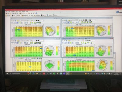
I got the thought to go back thru all my unmolested OEM GT\Bullitt tune files for 08-10 SO PCM & check all their map's axis scaling to see how the Ford engineers intended for this stuff to interface..............guess what I discovered..........this is exactly what Ford did so these maps will operate in synch & evenly, so the cell data points line up across the X & Y axis as close as they can be made thus the interpolation also between them.

So I set 1 up to use in Editor's compare feature to check my current tune file to see which maps that have been altered to then fix them. Found that the only map X\Y scaling axis that had been altered was indeed the Airflow\VCT\Configuration VCT load\TQ maps (also tested & found that all this scaling synch is tied to any tune map that is linked to the IMRC\VCT operation so all MAF LWFM & SD Airmass maps as well as all Spark Advance maps (mainly due to the BKT\MBT VCT IMRC maps).

So, I have gone & restored all Airflow VCT map's scaling back to the OEM scaling which will now restore proper map synching across all VCT\IMRC-related maps in my tune file & have flashed in revision #25 which now has all this restored (in the process I also reset the Knock Retard\Max Retard map to allow the PCM to pull as much as 8* of spark timing out across the board if needed for safety......up to 2.6* below the base borderline knock settings so the PCM can resolve most any tuning issues derived from this rescaling itself) back to OEM scaling process & to date all is working well w\o issue.

Now I will need to run driving datalogs under normal driving, part throttle & WOT operation to check the engine operation to ensure that the map scaling operation thru the map data cell sections that were out of synch prior aren't causing any unknown issues (all map cell data is still the same across the load% (Y) axis as this part wasn't altered......it's the map sections where the RPM (X) axis spread between columns was different is the concern.....depending on how well the PCM interpolated the same cell data points across the 2 different X axis tracks).

From all that I've seen\understood\learned, it shouldn't be much of a problem in the interim as the PCM should simply "retune" itself--thus the engine--to the new axis scaling changes......if the Knock Retard\Max Retard map settings are large enough to allow the PCM to do so in the map areas where operational cylinder pressures can get high enough to potentially induce\create knock\detonation--usually part throttle\WOT at 30% load & up in NA config (this area is 1 of the major tuning mistake areas IMHO that causes more engines to blow where some tuners keep these settings too tight to NOT allow the PCM to fully protect the engine w\ the thought to not lose too much HP\TQ during competitive racing or to maintain tuning "clout" thru the social "dyno wars". Competitive racing is 1 different aspect.... you should EXPECT this potential as a reality in this scenario thus has some merit.........because of competition so pushing every advantage.....but in a daily driver type of use.......?).

My engine, even though it's in excellent condition & runs w\ authority, still has in excess of 161,000+ mi on her so IMHO you don't do stupid.................especially when it isn't necessary.

PS edit--Now some may see all this as being nitpicky or out of touch in the tuning world............I see it as being a good, smart, safe & responsible tuner taking into account all variables to set this up to reflect any negative aspects until I can get around to doing the datalogging to fine tune all this so I can still enjoy driving my car & not be afraid\worried of hurting anything in the meantime. A BIG plus of tuning your own vehicles!
FYI..................

Here are some results of my car's recorded cat CE results captured this morning since correcting the map scaling in my tune file that I had found changed back to the OEM FoMoCo map X-Y axis scaling but still using all the same tuned map cell data in all maps unmolested:
B1 @ .035
B2 @ .059
CMBT @ 1,289*F
This is the best I've ever recorded these cat CE ratio results since initial install\break-in over 1 yr ago.

Now the main takeaway from this is not only how good the cats are working from an emissions perspective, but how overall efficient the engine is operating (an indicator of how well\accurate the PCM is measuring MAF then how well\accurate the PCM is measuring fuel thus is a window into how accurate the fuel stoich AFR setting is matching the actual fuel being burned to correct the EQ Ratio equation to true Lambda 1.0) w\o any issues w\ the spark timing or cam timing settings as currently set up. This data bodes very favorably towards this engine producing good efficient HP\TQ output since both derive from the very same combustion efficiency dynamics......all other variables being equal.

Kinda shows some relevance to the importance of all the PCM tune-related VCT\IMRC mapping maintaining\being properly synchronized so all mapping data points can be accurately interpolated by the PCM across the full operating range...........the OEM Ford engineers once again got all this right the 1st time so why\what reason was it altered.......especially if engine is not FI (the only reason why IMHO to rescale ANY of these SO PCM map's X-Y axis cause you HAVE TO in order to simulate above sea level atmosphere mass densities.....>100 kPa)?

Data results are very revealing............the devil is always hidden in the details.

Food for thought.......................
 

GlassTop09

Senior Member
Joined
May 24, 2019
Posts
1,142
Reaction score
525
Location
Farmington, NM
FYI.......................

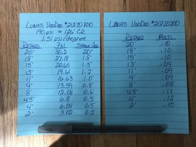
After getting confirmation on how the PCM goes about processing the VCT cam retard degree data from the Airflow\VCT\VCT IMRC load% map to the Spark\Advance\BKT\VCT IMRC Spark Adder map to correct the base BKT map then application of knock advance\retard to come up w\ the total amount of BKT spark timing to then compare to the Spark Advance\MBT & MBT VCT IMRC spark maps, I've been remapping my VCT IMRC Spark Adder map (pg 13, post #255) over the last 2 days using this IVC dynamic compression "schedule" that I calc'd up:
Lunati VooDoo Cam IVC Retard Spark Adder Correction.JPG
Using a typical static cyl compression number of 190 psi across the 126* of crank rotation based off the Lunati's adv IVC timing point of 54* ABDC (OEM cams adv IVC @ 53* ABDC for reference) at 0* cam\crank phasing reference, I came up w\ this scaling, estimating the amount of additional spark advance to add to BKT to make up for the loss of static compression from IVC retard based off my Airflow\VCT\VCT IMRC load% map's settings. Then divided the amount of spark adder by the amount of VCT cam degree retard to come up w\ the multiplier to use. Then once I got all plotted in map according to the Airflow\VCT IMRC load% map cell settings, I applied smoothing adjustments to clean up all transitions so it "flows" smooth thru PCM interpolation across entire map & into WOT settings (.80 load & up). So, in the end, some spark adders got increased above what I scaled while others got decreased but none of them were radically altered.

Note: This doesn't account for any piston velocity speed changes across the 126* of crank rotation (which will affect the final static compression numbers......would have been nice to have had real static compression numbers which would have incorporated all this)....only simple math to get some type of systematic numbering to use.

I went thru all this after discovering that my prior tuner, thru using the settings he used to set this map up w\ my Lunati VooDoo cams, had inadvertently locked the spark advance timing (set up so that the total base BKT\BKT correction\Knock Retard\Max Advance spark timing--max engine spark timing--exceeded the base MBT\MBT correction spark timing--this MBT reps the absolute max spark timing allowed & is last safety resort) thus the spark timing was held at this MBT map's corrected settings (which were on avg .5*-2.5* lower than the total BKT\BKT corrected\knock max advance timing cap) in most of the BKT\MBT maps from .10 load thru .70 load, so only WOT was found set up\tuned properly (total BKT was below the MBT thus allows PCM to apply some\all of the knock max advance settings based on knock sensor activity to "fine tune itself".....at WOT only). Since engine wasn't experiencing any knock, the settings were essentially "maxed out", thus locked.

This sucks big time......losing a LOT of potential drivability HP\TQ (power under the curve) set up like this!

I didn't want to mess w\ the base BKT & MBT tables or knock max advance tables (already tuned) but I could rework the VCT IMRC spark adders off my cam's VCT load% cam retard settings then add in the knock max advance table settings up front to come up w\ the total BKT corrected spark numbers to then work all them to come out just below the base MBT\MBT corrected numbers (gave a .5*-1* spread to ensure that PCM can use all the knock max advance timing as long as the knock sensors allowed (thus the PCM can fine tune itself above the base BKT\BKT spark timing). I made this easier by copying the corrected BKT VCT IMRC spark adder table into the MBT VCT IMRC spark adder table, so the Lunati cam's VCT spark profile is used on both sides to "cancel" it out, thus any future spark timing adjustments is simplified to the base BKT vs base MBT spark tables only, but the Lunati's VCT cam spark profile is accounted for on both sides now instead of just BKT.

This will unlock the PCM & allow it to advance spark timing between all base BKT\BKT corrected spark timing & the base MBT\MBT corrected max spark timing w\o crossing over MBT as it sees fit from knock sensor activity across the entire engine RPM operational range. The knock max advance settings were set @ 4* across the board (gives the PCM a fair amount of latitude to optimize itself).

Got all this worked out & saved in new revision #27 late last night then flashed in this morning. All checked out fine & took car out on maiden DC afterwards.......all I can say is......WOW!

All this time................
I just keep on finding stuff that ain't right in this tune the more I go over it.

Got back from DC & checked Mode 6 data & all I\M Readiness monitors completed except for EVAP (had tank filled >85%) & this time I can clearly detect the results of a quantified HP\TQ increase thru the cat CE ratio results (B1 @ .191, B2 @ .211 CMBT @ 1,250*F) from the reworked spark advance tables\increased airmass thruput. Gonna see if this stays at the high .1xx-low .2xx range which will verify this result.

From what I can tell, I think she's potentially got more in the tank than what I thought she had..........I really need to get my cabling situated to start driving datalogging part throttle\WOT & get her fully optimized.......safely.

Got a permanent solution coming for OBDII port relocation..........

Slowly coming all together...............

Also, found out after updating VCM Editor\Scanner Suite to vers 5.0.4, HPTuners is locking out any access to O2 sensors (so can't readjust\shut off\disable any O2 sensor DTC process data) until a training session is taken & subsequent tests are passed (have to get 100% right to pass on all tests) in order to get O2 sensor access unlocked thru interface. Your MPVI2+\MPVI3 interface is then assigned a device code to ID you\your interface to satisfy the EPA so that any infractions of CAA going forward in tuning found tied to your HPTuners interface will remove HPTuners from liability & puts all of it squarely on the owner\user of the ID'd interface. So, no more unfettered access. There are legal & sound reasons why accessing the O2 sensors as well as other sensors (MAF, MAP, injectors, EVAP, etc) thru the tune file is needed & the EPA is aware of this, so ICE tuners can still get legal access to all this stuff.......just not violate the CAA in the process by disabling\defeating any emissions devices or processes.

Went thru all the training\tests w\ ease & got my device code assigned to my MPVI2+ interface so is no big deal to me as I don't turn any of this stuff off\disable it anyway & don't tune for a living only tuning my own stuff.......I use it all as a tuning tool as all relates to the same combustion efficiency principles which dictates max HP\TQ as well as emissions compliance.

Just use the proper sized & certified emissions devices to handle the desired HP\TQ output...........everybody's happy.
 
Last edited:

GlassTop09

Senior Member
Joined
May 24, 2019
Posts
1,142
Reaction score
525
Location
Farmington, NM
The drive side is looking pretty darn good but the coast side looks like it needs just a bit more run time. I wander if that is the light noise you hear. It’s awesome the lighter pinion preload has worked as you suspected it would.
Hey Midlife Crises,

While driving my Stang the other day, I had a thought that the reason why I may not be feeling any resonance thru my MGW shifter in the way it's configured was due to the Delrin cover sleeve on my Raceseng Topology weighted shifter knob canceling it out. So, I moved my fingers down to make contact w\ the metal section of knob below the cover, then watched the speedo to see when I came within the MPH range that I could hear the faint resonance whine to then see if I also could feel it thru the knob metal.

Sure enough, when the DS rotational speed came within this range, I could feel the faint vibrations coming from the pinion thru the DS into the trans mounted MGW shifter handle & I also could detect them stopping just as quickly once outside of this 40-45 MPH range in either direction.

This finding just convinces me even more that my current resonance issues are pinion bearing related instead of gear mesh related thus the tuning fork properties as IMHO, a gear mesh related resonance should not reduce\fade as speed\load increases.......it should get worse......just like this did w\ the Richmond EXCEL 3.90 (3.89 actual ratio non-hunting) gears. But at the same time, I reused ALL of the same bearings that were previously installed w\ the Richmond gears (Motive Gear 8.8" install kit uses Koyo Hi-Cap bearings) w\ this Motive Gear F888390 (3.91 actual ratio full hunting) gears, so it appears that SOME of the Richmond gear whine was also coming from these same Koyo pinion bearings & races!

They didn't look like they were hurt in any way & had very low mileage thus wear on them, so I didn't see the need to change them out.........

Another lesson learned...........if excessive resonance is detected w\ a gear set install, always change out all bearings\races w\ the gear set as well to ensure that you cover ALL possibilities at the same time.

The good thing here is that this resonance whine is very low to start with & is getting quieter the more I drive the car so it will quiet itself once the offending bearing(s) finish wearing in.

Thought I'd mention this to let you know what I found.
 
Last edited:

Midlife Crises

Senior Member
Joined
Jul 20, 2019
Posts
1,854
Reaction score
1,265
Location
Fairbanks, Alaska
stopping just as quickly once outside of this 40-45 MPH range in either direction
Interesting. What I remember from a long ago Turbine and speed reducer vibration seminar says you are passing through the resonant frequency of a component. Makes sense it could be the bearing especially when Ford altered the roller count of the Hi-load bearing reportedly to make it quieter at hi-way speed. I still like the idea of setting the preload to the light side of spec and using the long proven solid spacer and shims. I made it through the summer with the 4-10s and the “good” bearing with only light whine at cruse. You mention replacing all the bearings while your in there and I fully agree. It is also imperative to remove all the shrapnel and metal flake wherever it is hiding. I disassembled the tru-trac for cleaning and have no doubt the trash inside would have killed yet another set of bearings. Only thing left to do for the diff is to step up from 80-90 to a heavier lube.
Thanks for sharing your notes.
 

GlassTop09

Senior Member
Joined
May 24, 2019
Posts
1,142
Reaction score
525
Location
Farmington, NM
Makes sense it could be the bearing especially when Ford altered the roller count of the Hi-load bearing reportedly to make it quieter at hi-way speed.
Now THIS I wasn't aware of until now!
This info settles this aspect going forward for me........

Thanks for sharing as well!

:beer:
 

GlassTop09

Senior Member
Joined
May 24, 2019
Posts
1,142
Reaction score
525
Location
Farmington, NM
Also, found out after updating VCM Editor\Scanner Suite to vers 5.0.4, HPTuners is locking out any access to O2 sensors (so can't readjust\shut off\disable any O2 sensor DTC process data) until a training session is taken & subsequent tests are passed (have to get 100% right to pass on all tests) in order to get O2 sensor access unlocked thru interface. Your MPVI2+\MPVI3 interface is then assigned a device code to ID you\your interface to satisfy the EPA so that any infractions of CAA going forward in tuning found tied to your HPTuners interface will remove HPTuners from liability & puts all of it squarely on the owner\user of the ID'd interface. So, no more unfettered access. There are legal & sound reasons why accessing the O2 sensors as well as other sensors (MAF, MAP, injectors, EVAP, etc) thru the tune file is needed & the EPA is aware of this, so ICE tuners can still get legal access to all this stuff.......just not violate the CAA in the process by disabling\defeating any emissions devices or processes.
FYI...............

Have taken a closer look at all this & am updating to say that HPTuners is locking out all parameters to\of components that are monitored according to the EPA sanctioned OBDII I\M Readiness emissions component list, so more than just the O2 sensors (if you hover the mouse pointer over a setting that is greyed out & the link "Parameter Access" shows up in lower right side of GUI, access to it is locked out & user will need to get certified to get device code assigned to interface by HPTuners to unlock the software to gain access).

The good thing is that it looks like the IMRC system (CMCV's) isn't included in this (not part of the EPA I\M Readiness emissions monitored components list---the only component in my tune that is "broken", but according to all my recorded OBDII cat CE ratio results data from a fully functioning & unaltered PCM catalyst OBDII monitor of CARB\OBDII-cert EO# D-193-140 MF #5461336 TWC aftermarket cats assigned to car's legal VEI EFN (which satisfies the EPA's legal term "certified condition" which actually supersedes "original condition"....original condition is to be used instead ONLY if certified condition can't be quantified), it being "broken" also shows\proves to not adversely affect emissions either......stated by the letter of the CAA regs.....thus is supposedly deemed by EPA to be "allowed reasonable conduct"........also verifies any other non-OEM component(s) being used upstream of said legal & passing CARB-cert TWC cats as "not adversely affecting emissions" as well thus exempted\allowed). Which also according to the CAA regs, any CARB-cert emissions device\component, whether OEM or aftermarket, has an exemption granted from EPA regs due to CARB regs being stricter than EPA regs thus is also granted favorably towards my situation as long as the said component\device is unaltered from its original design & function, regardless of whether car is manufactured to be sold\operated under Fed OBDII or CARB OBDII guidelines.....car can only be held to the EPA regs in effect of MY when car was manufactured\granted the original EPA CoC sale document (in my case, the Fed OBDII EPA emissions reduction thresholds circa 2009 granted to FoMoCo as tailored to comply w\ the State of New Mexico's addendum of the Fed EPA regs where car was destined to be initially sold......Bernalillo Co......car is currently registered in San Juan Co which is exempt) thus the CARB-cert TWC cats in use are certified to pass current MY CARB OBDII emissions gms\mi thresholds which are far stricter than the EPA regs at time of car MY EPA CoC sale grant thus is deemed favorably granted as well.......
Since I am also an individual legal US citizen\taxpayer (which according to the EPA tampering regs, the EPA will show the most favorability towards if evidence of "reasonable conduct" to comply is\can be demonstrated) instead of a US business of commerce (who has a legal obligation to fully comply w\ all Fed FTC regs including EPA CAA when selling products to the general public......"for off road use only" product labeling is not enough to deem reasonable proof of compliance.....never has been under the law) & have in hand the amount of creditable evidence that is fully admissible in a court of law, I'd wager that the EPA won't waste their time worrying about trying to prove little ole me to be guilty of breaking the CAA in regards to my '09 GlassTop & my tuning in her PCM when there are SOOOOOOO many other available, easy & much lower hanging targets to pick from.......... All info is easily accessible to the public at www.epa.gov.......................

All contained in a neat envelope along w\ all supporting documentation (including MF 5 yr, 50,000 mi CARB\EPA mandated cat warranty documentation w\ car's MY\VIN & mileage at time of install of said cats documenting CARB approved legal reason for aftermarket cat replacement\install signed by myself & On3 shop who performed cat replacement\install along w\ picture of finished install according to CARB EO# document designation of UL, UR) w\ my car's VIN & VEI EFN wrote on it & stored in car's glove box for evidence........

I sleep pretty good at night. Sheesh......night's almost over so off to bed........
 

GlassTop09

Senior Member
Joined
May 24, 2019
Posts
1,142
Reaction score
525
Location
Farmington, NM
FYI.........................

1st, refer to post #302 to gain inference into the following.......................

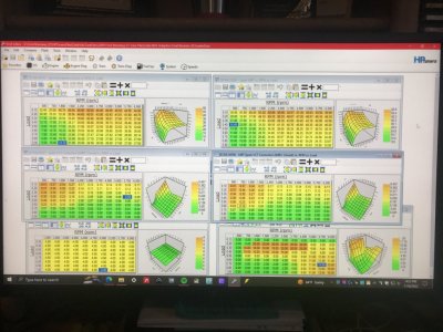
As of now, this is where my 4.6L w\ these Lunati VooDoo cam's optimized VCT cam timing profile as set up by the existing Airload\VCT\VCT load% map (sets max VCT cam degree retard to use according to load% & RPM.....not the max VCT cam retard limits--these Lunati's are a NSR & full VCT-compliant camshaft which they can be retarded to full VCT 60* limit w\o incurring piston-to-valve contact--so these are intentionally capped to a max of 20* retard to maintain a higher avg static cyl compression pressure profile across all RPM range between .10 airload thru .70 airload--where you can take advantage of the lower airloads w\o much worry of pre-ignition\detonation--cyl filling is still somewhat limited by TB TPS angle not being fully open--like it would be during WOT. BTW.....this is still the same base airload VCT load% map prior tuner set up for my Lunati cams...........) & the now more optimized Spark\Advance\BKT\BKT VCT Spark Adder map (set up to counter the VCT retarded cam IVC timing during compression stroke from retarding cam EVO to increase TQ application during power stroke which reduced static cyl compression pressure build by using extra spark advance timing over existing base BKT spark timing map to "make up" the lost static pressure to gain "net TQ increase" thru PCM use of VCT cam timing operation). Then copied all of the corrected BKT VCT spark adder map settings to the Spark\Advance\MBT\MBT VCT Spark Adder map (this now has PCM using the SAME VCT optimized cam timing profile in both existing base BKT & MBT spark advance maps so this "removes" the tuner imposed inadvertent spark advance timing "cap" to his own BKT spark advance map work that was set up by using a different BKT VCT spark adder map than MBT VCT spark adder map thus using 2 different VCT cam timing profiles based off the SAME Airload VCT load% cam retard timing map--OEM maps also do this as well--that clashed w\ each other, which when I ran spot checked calcs of the numbers thru this section of both BKT\MBT spark advance maps, I found the base MBT + MBT VCT adder spark timing was LOWER than the base BKT + BKT VCT adder + knock max advance spark adder maps COMBINED across most of the RPM range between .10 airload thru .70 airload, thus "capped" overall spark advance timing so all the tuner added extra BKT VCT spark advance adder & knock added advance spark timing was not used at all by PCM since the MBT maps are the absolute spark advance timing LIMITS--MBT spark advance timing tables are also used by PCM TQ Management to calc engine TQ output based off airload\fuel calcs across RPM's so this was also capped to same MBT spark advance timing tables that also capped BKT spark advance timing tables outside of WOT thus held TQ Management back some......):
09 Ford 4.6L 3V VCT Cam Profile GlassTop09 Lunati VooDoo Cams Spark Control.JPG

(continued in next posting)
 

GlassTop09

Senior Member
Joined
May 24, 2019
Posts
1,142
Reaction score
525
Location
Farmington, NM
(continued)
Here is the prior setup for comparison:
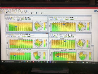
09 Ford 4.6L 3V VCT Cam Profile On3 Lunati VooDoo Cams Spark Control.JPG
Note in prior posting notice also that the RPM scaling in all maps except the Knock Max Advance map is synched (same scaling) as opposed to this picture & also notice that in both pictures the .80 airload thru 1.00 airload of both BKT\MBT VCT spark adder maps is still at 0 (cancels any added spark adder to base BKT or MBT spark tables to regain lost static cyl compression from retarded cam IVC so prior tuner has added this into the base BKT spark map only at .80 thru 1.00 airload) to maintain prior tuner's WOT tuning using existing base BKT spark timing w\o BKT VCT spark map adder + knock max advance adder against existing base MBT spark timing w\o MBT VCT spark adder (which has total base BKT + knock max advance timing LOWER than base MBT spark timing alone so PCM has added all BKT + knock spark advance timing as well as a higher optimized TQ Management calc'd engine TQ output at WOT since MBT spark tables are higher & TQ Management USES the MBT spark timing tables in its calcs.......all using the SAME Airload\VCT\VCT max cam retard timings from the same map across BOTH base BKT & MBT spark tables thus engine will respond faster thruout the WOT run than it would from .10 airload thru .70 airload, all other things being equal.

I then painstakingly reworked all the BKT VCT spark adder mapping (thus the VCT scheduling I created in post #302) so the actual results from base BKT + BKT VCT spark adder + knock max advance combined would exactly match the prior tune's existing "capped" base MBT + MBT VCT spark adder at .10 thru .70 load low RPM's thru 3,000 RPM then blended thruout the rest across .10 thru .70 load above 3,000 RPM's coming out closely matching as well but also smoothly blend into the existing .80 thru 1.00 load WOT section w\o interfering w\ it, then copied all this into the MBT VCT spark adder map so this has both BKT & MBT using the SAME optimized Airload\VCT\VCT load% cam retard timing mapping in the SAME manner across both sides thus also improves overall PCM TQ Management calc performance thru MBT spark tables as well, then added .50* across the base MBT spark timing map to set the rough avg .50* to 1.00* higher spread between combined BKT\BKT VCT\max knock advance to combined MBT\MBT VCT spark advance to ensure that PCM ONLY uses ALL actual BKT spark advance combined timing & stay off ALL of the MBT spark timing tables so PCM TQ Management calc'd engine TQ output will ALWAYS be more than actual engine TQ output so TQ Management will ALWAYS fully optimize the actual engine TQ output across ALL the engine's entire airload & RPM operational range as long as the knock sensors agree since max knock spark advance timing is ALREADY accounted for in combined BKT (for safety reasons). So, the total avg spark advance past 3,000 RPMs is overall advanced approx .50* thru 1.0* over the prior tune from .10 load thru .70 load.......thus very little......but at these airloads a little can put out a fair amount of TQ that will easily be felt thus all drivability will be much improved thru both combined BKT timing improvement AND improved TQ Management performance from both the improved VCT spark adder to VCT airload cam retard timing as well as higher overall combined MBT spark timing vs combined BKT spark timing.......w\o touching anything in TQ Management or Indicated Engine TQ mapping or Knock Sensitivity Threshold mappings or anywhere else.

So far, all testing done to date since doing all this over 2 more revisions since post #302 (on revision #29 now) is positive, engine has a lot more authority (power under the curve) in all areas below WOT & can't detect any presence of knock (have also reset Knock Retard to apply any detected cyl spark retard on a per cyl basis--the cyl\cyls that actually reported knock--instead of the OEM tune's set std global basis--a holdover from the 4.6L 2V which had only 1 knock sensor thus could only apply knock on a global basis--that prior tuner left as OEM set--since SO PCM's are coded to detect knock on a per cyl basis anyway......this reduces the amount of total engine HP\TQ loss from a single cyl knock event.....) so this is why I'll need to run some driving datalogs of part throttle\WOT to see if the knock sensors are reporting any knock as I can't tell.....engine doesn't show\demonstrate any signs of TQ letup\backoff thruout the .10 load thru .70 load region that I dared to use but I'm also not pushing it either until I can get confirmation.....if knock sensors are quiet\happy then this is confirmation that ole girl has indeed got more in the tank as the engine will be operating on the total combined BKT\BKT VCT & knock max advance timing cap thruout all engine load & RPM's w\o complaint.

Then the ONLY maps that need to be adjusted will be the BKT\MBT VCT spark adder maps to fully optimize the VCT cam timing operations to fully optimize total engine HP\TQ output as long as airload\fuel can keep up......which shouldn't be an issue at all (CAI is a FoMoCo "Bullitt" 83mm w\ calc'd calibrated MAF transfer max rate @ 50.807 lbs\min airflow @ 6,250 RPM's.....equivalent to a 6.4L engine at 100% SL VE at same RPM's--this 4.6L engine's max 100% SL VE is 36.28 lbs\min at same RPM's......since I've also added a S&H Performance Fuel Pump 8 gauge awg Wire Upgrade mod--overkill I know, but if I'm going thru all the trouble to run this mod I'm running the largest gauge wire run that JeremyH sold w\ a 30a Slo-Burn fuse installed matching max FPDM current output w\o causing FPDM overcurrent protection kicking in so DC current to stock pump can go up to as much as 30a if needed instead of topping out at 15a or less due to excessive heat buildup thru the OEM 16 gauge awg wire feeding the FPDM, the kit cost was too good not to--to stabilize current flow to stock OEM fuel pump so I don't expect it to drop off anytime soon).

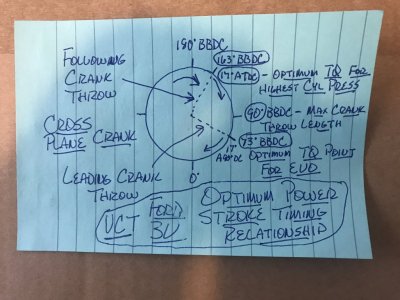
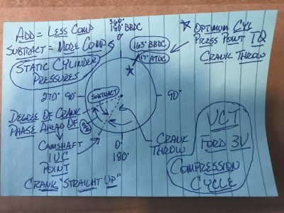
Here are provided some drawings of a Ford 3V VCT operational design concerning optimal TQ output off cam retard timing\spark adder to recover retarded cam IVC timing static compression loss:
Ford 4.6L 3V VCT Optimum Power Stroke Timing Relationship.JPG Ford 4.6L 3V VCT Intake Compression Cycle.JPG
So, w\ my Lunati's set for max cam retard cap of 20*, this puts the cam's adv retarded EVO at 68* BBDC which is 5* past the adv 73* optimum BBDC point to allow 2 cyl's crank throws to apply force to the crankshaft briefly during the power stroke before the leading cyl crank throw's pressure is bled off piston thru EVO event & now w\ increased IVC spark adders in BKT\MBT VCT spark maps to adequately regain\increase lost static cyl compression from retarded cam IVC timing, net engine TQ output should also increase thru both improved combined BKT\knock advance maps & TQ Management thru the improved combined MBT spark maps co-existing in harmony w\o interference from each other.

There is no way this can happen w\o VCT & no way this can happen thru BKT or MBT maps w\o using the VCT spark adder maps to compensate for the retarded cam IVC timing during VCT operations.........not even using FI........can only "mask" the loss thru using extra boost to compensate for it.

I have recorded evidence of some tuners recommending folks to zero out these BKT\MBT VCT spark adder maps to optimize engine HP\TQ..............using the VCT load% cam retard timing map at the same time............... FI I can see why 1 would do that due to the rescaling of all mapping to simulate air lbs\min & densities >100 kPa, but a NA 4.6L engine? You're ASKING for a TQ loss if you do this...regardless of camshaft choice used, including OEM cams....I tested this out myself early on in my short tuning time stint & found this to be true so this ain't some "talking point". The TQ drop was VERY noticeable.

This is just a sampling of just how important VCT is to this engine's max HP\TQ output capabilities.

Waiting on OBDII relocation install to start driving datalogging.......

Enjoy!

PS edit--almost forgot......after initial DC, all I\M Readiness monitors completed except EVAP & recorded Mode 6 Catalyst CE ratio results as follows thru MF #5461336 cats:
B1 @ .102 engine idle LTFT @ -2.3%
B2 @ .133 engine idle LTFT @ 0.0%
CMBT @ 1,313*F (all w\ included EVAP purge cycling of unmetered fuel vapors & air added to LTFT's)
So initial results also show a potential emissions output improvement as well due to improved engine combustion efficiency on top of it all.
 
Last edited:

GlassTop09

Senior Member
Joined
May 24, 2019
Posts
1,142
Reaction score
525
Location
Farmington, NM
Now that I got some sleep time put in...........................

I'd also be remiss to not type in here of the 1 mistake I made during my short tuning adventure............

Back in revision #8 I had correctly made changes to my tune file concerning placement of IMRC open map data into IMRC closed maps so PCM will use the more aggressive OEM data that correlates to the IMRC control (CMCV's) being in the open position (which follows the same dynamics as removal of CMCV's & disabling IMRC control in tune) since the PCM is coded to follow the I\M Readiness OBDII DTC setup (all IMRC Control B1\B2 Stuck Open\Close Failure DTC's (P2004\P2005; P2006\P2007) are recorded in PCM for diagnostics, but only the IMRC Control B1\B2 Stuck Open Failure DTC is set to light the MIL.....not the IMRC Control B1\B2 Stuck Closed Failure DTC so this is by Ford design to intentionally ignore the IMRC Control B1\B2 Stuck Closed Failure DTC & not alert the user so in event of failure of any IMRC B1\B2 Stuck Closed Failure the PCM defaults all IMRC controlled maps it controls to use the IMRC closed maps thus their data until this is fixed (tuned for emissions\daily driving.....not performance) thus the PCM also will default to this same pattern when the IMRC control is disabled in tune file.

Later on, I somehow forgot all this & made an erroneous judgment when dechipering some other tune issue & changed the previously correct set up LWFM & SD MAP at Zero Airmass\SD MAP per Airmass Open map data copied into all LWFM & SD MAP Airmass IMRC closed maps then corrected the LWFM Open data's TP 0% row using copied LWFM closed map's TP 0% row data to fix this map so engine would idle properly if MAF sensor failed, back to all IMRC Closed map data thinking that the OEM LWFM Closed table data is calibrated to the OEM calibrated MAF transfer tables so all IMRC closed map data goes as well.

While trying to figure out if the IMRC control itself operated the SD MAP Airmass Y-axis scaling, I realized that it is the commanded Airload VCT load% map data that PCM uses to determine which row of SD MAP Airmass data values to use in all SD calc's (read primarily ETC here) according to the amount of VCT cam angle retard commanded (another variable that VCT control affects thus importance of VCT use w\ this engine) so ALL of this data has to be calibrated to operate in harmony w\ the MAF transfer tables which also includes the IMRC open maps.....including both the IMRC Open\Closed LWFM maps too!

I was half right..............but this still makes me wrong! Car operated just fine otherwise but VCT actually was using SD map data that was calibrated to a closed CMCV thus not calibrated to an open CMCV scenario that is a better match to CMCV removal......which also included the LWFM tables as well.

So, part of the 2 latest tune file revisions done included restoring all this back to revision #8 setup thus all is now setup correct for IMRC\CMCV removal in tune file.......once again.

Yep, I do realize that at times I might "over process" already made decisions (called 2nd guessing in layman's terms), but I've also learned to continue to go thru a set analysis process check (too many yrs doing this type of work in the petroleum industry thus has become a natural habit) to always go back over any work I've done prior to make sure that what I've done is correct......thus I always do "back check myself"........

This habit has never failed me to this day...............

Also, I made a couple of tweaks to the airload VCT load% map after doing the RPM rescaling of this map to match the RPM scaling of all Spark Advance maps. A cell opened up between the new 750 RPM & old 1500 RPM column in .20 load row, so I input a 20* max cap in this cell so PCM will start applying cam retard timing adjustment immediately as needed when PCM switches from Idle Control into Borderline Spark Control & in .70 load row I inputted 2* of cam retard timing in the 750 RPM to 2250 RPM columns (were 0 before) to have PCM also start applying VCT cam retard in this load row across these RPM columns to better blend thus transition into the already set up .80 load thru 1.00 load rows (WOT).

We'll see how all this goes soon.

FYI..........................
 

GlassTop09

Senior Member
Joined
May 24, 2019
Posts
1,142
Reaction score
525
Location
Farmington, NM
FYI.........................

In post #308 I posted a picture of a sketch I drew up showing the optimum point in power stroke that 2 cylinders can start exerting their force on their respective crank throws of the crankshaft, so I have now calc'd where the optimum crank degree is for the leading cylinder to open the exhaust valve to do 2 things 1.) optimize the force energy of both cylinders for max TQ output & 2.) still have enough exhaust energy left in the leading cylinder to establish good exhaust scavenging velocity flow thru primaries to enhance cylinder filling during overlap.

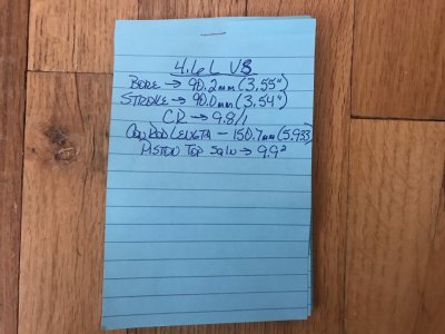
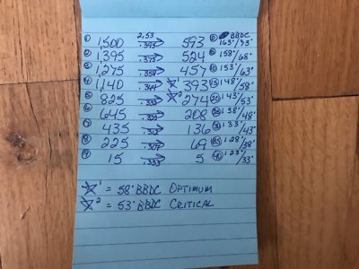
Here are the results I have come up with for this 4.6L V8's OEM stroke & CR length using Wallace Racing's new "Calc Piston Position using Crank Angle" calculator (to locate the piston top from TDC at CA of leading cylinder vs following cylinder to then calc the cylinder pressure curves of following cylinder--highest--to cylinder pressure curves of leading cylinder--lowest--at 5* increments of rotation using a cylinder pressure of 1,500 psi--equivalent to a typical race engine's peak cylinder pressure @ 163* BBDC or 17* ATDC during the power stroke.......the 0* starting point):
Ford 4.6L V8 Engine Specs.JPG Ford 4.6L V8 Optimum Power Stroke Using Lead Follow Cylinders.JPG
According to my calcs, the optimum EVO point for our OEM 4.6L V8 to harness max TQ output during power stroke is at 58* BBDC for leading cylinder\148* BBDC for following cylinder vs the absolute critical point at 53* BBDC for leading cylinder\143* BBDC for following cylinder. This equates to 15*-20* max crank rotation of double cylinder participation during a power stroke event thus maxing out the overall TQ output potential.

Anything past this point is very poor diminishing returns as far as TQ output is concerned but the far larger loss will be high enough cylinder exhaust gas pressure left to create good exhaust scavenging velocity at high enough speeds & not create excessive deltaP flowing thru cats or "FFE" (which will reduce the scavenging velocity in the primaries thus affect cylinder filling capacity during overlap) to optimize cylinder filling during overlap. This is called "reducing pumping loss" & is only good for emissions thru excess EGR flow lowering combustion chamber temps thus NOx\maybe some MPG gain due to reduced avg air\fuel fillage thus usage......which also reduces TQ output.

So, using this info I can figure out the optimum VCT cam phasing degree settings to use in VCT load% map to match these calcs based on my Lunati VooDoo cam's adv EVO point (this is ground in cams to match crank phase or "straight up" at 0* phase), so their adv EVO is 88* BBDC thus 88*-58* = 30* max cam phase retard to optimize TQ output during power stroke. My tune's VCT load% map is currently set for 20* max.......

Revision #30 is in process of getting the Airload\VCT\VCT load% map's settings revamped to meet these results..................

Yes, I just keep on finding things to change\optimize in my tune file.............

Enjoy!

PS--Forty61, not there yet but I'm still working on getting her there........ Thanks for the kind words...........:beer:
 
Last edited:

GlassTop09

Senior Member
Joined
May 24, 2019
Posts
1,142
Reaction score
525
Location
Farmington, NM
FYI.........................

In referral to post #310:

From coming up w\ the optimum EVO point in crank degree rotation to optimize the max TQ output of using 2 cylinder's combined force on crankshaft rotation during the power stroke, I can now use this to optimize as much of the engine's TQ output for drivability as I can between .10 load thru .70 load rows of my tune file's BKT spark mapping thru using the BKT\MBT VCT Spark Advance Adder map settings & Airload\VCT\VCT load% cam phase retard map settings (will optimize the actual engine's net TQ output in addition to optimizing ETC's\MAF's airload calcs & TQ Management's TQ calcs--which ensures actual engine's optimum TQ output is achieved). The rest is then gained\lost thru knock sensor activity spark advance\retard........this is how Ford designed\intended all this to be used w\ VCT.

I've already finished revision #30 & have already flashed into car & have already ran initial DC.......will post these results in a minute.............

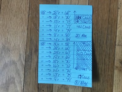
Here is provided a sketch of the TQ distribution according to the prior VCT load% map using 20* max retard vs the new VCT load% 30* max retard:
Ford 4.6L V8 Optimum Power Stroke Usage from VCT Cam Retard.JPG
Note the "shaded" areas denote the amount of map cells that are using double throw TQ application referenced from the 163*\73* BBDC EVO point where it starts. My map has 59 map cells between .10 thru .70 load that have a cam phase retard setting in them greater than 0 (no cam phase retard applied in these cells).

You can see that from just adding the 10* extra degrees of cam phase retard past 20* to hit the optimum 30* max cam retard 148*\58* BBDC EVO point has essentially flipped the engine's max TQ application usage in this area of my tune file's VCT load% map from approx 1\3 to 2\3.........this is ALL MECHANICAL TQ gain, the rest will come thru optimizing the BKT\MBT VCT spark advance adder maps to optimize the "net" max dynamic cylinder pressures based off the same VCT cam phased EVO retard & knock sensor activity to fully optimize\match the camshaft's valve timing point potential to the crankshaft's mechanical rotational potential.

The whole purpose of why I do all this.......to fully optimize my lowly 4.6L's HP\TQ output in NA config......across the board. No stone left unchecked..................

Now the car drives much more linear in its throttle responses......so much so it felt like it wasn't doing much as I shifted thru the gears......until I looked at the speedo! The engine's TQ output is now so linear\optimal thru this section of my tune file's mapping, it isn't requiring the PCM to make as much of a TB TPS adjustment to make up load when shifted into 3rd gear during normal accelerations to make the necessary TQ called for (when I could hear the engine tone change & feel car surge). This threw me off at 1st as I had gotten used to hearing\feeling this cue until I checked the speedo & saw that I was already north of 60 MPH & needle was steadily climbing......the car was accelerating faster than before but the power output was so smooth it didn't SOUND\FEEL like it..........I haven't optimized the BKT\MBT Spark Advance Adder map settings yet either.......just using the roughed in settings at the moment.

The reason why this is so, is due to me taking full advantage of this engine's mechanical TQ potential thru its base crankshaft design (a cross plane crankshaft using 90* crank throws which will allow 2 cylinders to apply their mechanical force to the crankshaft for a specified moment during crank degree rotation of power stroke) to optimize the amount of expansion energy created from combustion to make max crank twisting force by matching the camshaft's valve timing EVO point to the crank degree's optimum piston position to make full use of this available force in both cylinders.......that we call TQ........or using a better term........available TQ or "under the curve".

Dyno graphs don't show the full picture of all this........only what is measured at WOT.

Now when an engine can make\apply the same power by being more efficient at doing it, it needs less load% thus will need less fuel thus this should translate into being more MPG efficient as well as being more emissions efficient (increasing power to GVWR weight ratio)..................when all is set up well & PCM is operating fully in Closed Loop-Normal Mode thus is using the proper fuel stoich AFR setting to measure Lambda 1.0 that matches the actual fuel being burned & properly operating NB\WB O2 sensors for accurate O2 feedback data.

With this said, here are the Mode 6 Cat CE Ratio results I recorded from this DC done yesterday using only the corrected VCT cam retard load% map settings in tune file--all else the same (which should be said also that this corrected VCT cam retard load% map settings also invoked a different section of SD MAP at Zero Airmass map--calc's calculated absolute manifold pressure--& SD MAP per Airmass map--calc's total airmass at calc'd absolute manifold pressure\calc'd baro pressure---the deltaP across the effective area\predicted throttle area of the TPS angle of the TB being used as recorded in the TB section of tune file, according to the amount of VCT cam phase retard used), by ETC & TQ Management along w\ the LWFM airmass tables to then check the same airmass load calcs from generated MAF tables from MAF sensor input across the very same actual physical effective area\predicted throttle area of the same TPS angle of the same physical TB being used for agreement, which then the PCM will apply the backchecked\corrected results w\ the necessary BKT engine spark advance applied thus engine TQ output:

B1 @ .055 idle LTFT -3.1%
B2 @ .074 idle LTFT 0.0%
CMBT @ 1,270*F
All over the very same exact 37.6 mi DC route I use driving it in the same direction\manner each time so that the results gained are as relative as I can make them to be w\ any prior or later DC results to evaluate any tuning changes\effects seen\noted.

The PCM will only learn\dial itself in from here........if all pertinent supporting settings are left alone & operating intact.......none of this causes HP\TQ loss in any way. Usually, PCM will be adjusting constantly to the surrounding environmental changes going on while the engine is running.

This is why I use the initial DC captured Mode 6\live data to determine my tuning as well as engine's "efficiencies" as this results data is the closest window I can relate to the raw, uncorrected tune settings in tune file.......that I entered, to see how well I have all set up in tune to reach my tuning goals w\ car's engine. Driving datalogs will provide the rest of the engine's operating component\internal data to make further adjustments as needed.

The closer those initial cat CE ratio numbers are to .000 is indicative of how well\efficient the engine is set up\running thus how efficient the engine is in making the max HP\TQ that it is putting out........not how much HP\TQ the engine has lost!

Enjoy!
 
Last edited:

GlassTop09

Senior Member
Joined
May 24, 2019
Posts
1,142
Reaction score
525
Location
Farmington, NM
FYI..........................

After evaluating performance & looking back over all Spark Advance VCT adder maps along w\ Airflow VCT load maps I revamped all this again & have flashed in revision #31 & have ran initial DC & another performance evaluation drive. Here is the current rev #31 mapping:
2nd-09 Ford 4.6L 3V VCT Cam Profile GlassTop09 Lunati VooDoo 21270700 Cams Spark Control.JPG
Now we're starting to get some tangible & very good response out of the ole girl TQ-wise across the entire .10 load thru .70 load drivability range....... At this stage I believe we've caught up w\ the lost static compression loss thru VCT retarded cam IVC timing thus are now actually experiencing true net dynamic compression gains above this point to enhance the extra mechanical TQ output gained from VCT retarded cam EVO in the optimized EVO points of the newly reworked Airload VCT load% map for double crank throw force\TQ application during power stroke (163*\73* BBDC start thru 148*\58* BBDC end as shown in drawing in post #311).

Engine TQ output is increased right out of the gate & is progressively being applied thruout w\o any hint of dropoff\engine clatter or rattling so can only deduce at this time that no knock is going on thus total BKT combined spark advance timing including the 4* of knock max spark advance is properly capped out (all riding just .5*-1* below the MBT combined spark advance timing settings......where I set it all to hit thus as they should be).

Initial DC Mode 6 Cat CE Ratio\live data results as follows:
B1 @ .109--idle LTFT @ -4.7%
B2 @ .160--idle LTFT @ 0.0%
CMBT @ 1,281*F (most of the -LTFT% numbers is due to EVAP purge cycling during low speed\idle operation where PCM performs EVAP purging the most.....for some reason it always is showing up most thru B1 side more than B2. But as long as B1 LTFT is cutting fuel less than 5% & B2 LTFT is holding steady at\around 0.0% this indicates IMHO that the PCM's A\F control is pretty much spot on.....hella feat for NB O2 sensors).

Drives like a whole new car.........acceleration is very much improved across the board & all this is coming from just an avg 1.2* increase at RPM's below 3,000 then tapering down to an avg .6* increase above 3,000 over prior BKT\MBT VCT spark adder mapping. This is a wholly different feeling of this engine's TQ application when it is done using the Ford provided BKT\MBT VCT spark advance adder tables (that too many tuners disable entirely) because this is all tied to PCM using VCT operation--not just base BKT\MBT spark advance timing--to model all the cam's valve event timing\positioning as it phases the crankshaft\piston position relative to the camshafts GI valve timing points across the engine load% & RPM operating range. Nothing else was touched in tune as all other found (posted in earlier postings in this thread) items have already been addressed prior me starting to get into the spark advance\knock & VCT side of my car's tuning.

All the PCM does is phase the crankshaft degrees thus piston position in bore relative to the camshaft's GI valve timing points according to what it is programmed to do.........the tuner has to make it all work optimally w\ the camshafts installed........the 1 large area of contention here for a tuner is TIME......to do all this correct a tuner has to put in some time, usually over several revisions, to study the cam card to discern the GI advertised valve timing points @ .006" lift (what Ford uses to set up VCT) at straight up 0* reference to then understand where the optimum mechanical TQ strengths\weaknesses of this engine's cross plane crank design is w\ it's displacement to then set all up to optimize as broad\much of this area as you can w\o killing off the induction side (cam GI IVO, EVC positioning which includes GI valve overlap) to maintain good engine airflow\cyl filling thus is a balancing act..........

IMHO you NEED to use ALL of the Ford coding provided as Ford INTENDED for it to be used to get all this 4.6L 3V has in it in NA config........even when FI is used......otherwise you're leaving extra HP\TQ on the table......period. No getting around it.

It is FI use that IMHO is making some tuners too lazy to tune this properly w\ this 3V........too easy to just use boost pressure to get around doing the proper tuning thus is "masking" these tuning deficiencies. Also have to say that some customers don't want to pay for the necessary time it will take a tuner to properly do all this either, especially when a dyno is involved......only want to get\know a peak HP\TQ number.

So, this does cut both ways........................

Add in now that this 3V platform is old tech & the Coyote platform taking precedence, IMHO just get\buy the tuning software\interface platform of your choice (while you still can), take\make the time to learn it & this SO PCM & do all this yourself as future tuner choices are just gonna get fewer & less to pick from going forward.......as I also believe that this is gonna be the way forward in the future ICE tuning world anyway. All those that think going back to carb-equipped ICE to get around the EPA is IMHO smoking stuff......better be paying attention to Holley's development of their Sniper, Terminator & Atomic EFI systems to replace carbs.........they'll most certainly be EPA-approved in time & carbs will be banned.......mark my words. I believe the EPA's goal is to push all this down to the individual consumer level & get it out of the business's hands as by that time the goal is for the overwhelming bulk of the populace to convert to alternatives.......such as electric vehicles for starters along w\ much improved clean mass transit systems in all metro\suburban areas to discourage\eliminate the need for folks to have an ICE vehicle........which doesn't include a LOT of us old baby boomers......so IMHO get used to it, our time has come & is quickly passing on so enjoy what's left of it is what I intend to do.
The EPA will simply be counting on a lot of us old geezers to not want to go thru the trouble of learning\doing self-tuning thus will achieve their objectives if they can shut down enough tuning\performance parts businesses that also don't want to go thru the certification processes to provide\sell to the public, then be held liable for CAA infractions due to someone else's poor maintenance\parts design\installations. Have noticed some online tuning shops are now having customers sign addendums up front that the tuning\parts provided are\will not be used on street-driven vehicles & no I\M Readiness components or processes will be disabled, altered or removed......prove strictly for off road racing use only......to protect them from liability claims due to potential customer CAA infractions.

From here I've already started work on revision #32 in which I will now bring all this into the WOT side to incorporate as much of the double crank throw TQ application as feasible into WOT.........but application of it will not be done until I get my permanent OBDII port relocation work (got a Dummy OBDII Port Relocation harness for my MY Stang coming) done to get baseline datalogs to know where I'm at & my Zeitronics ZT-4 Dual WB controller w\ dual display setup (already had this in hand for the last 4 yrs....planned for a future FI install that I have now ruled out but I need this to be able to self-tune MAF & fueling accurately in CL & OL PE) installed & set up........

Would love for some shop to set up an extra dyno cell for rent in my area...........

So, I'm gonna keep her where I got her for now & enjoy the newfound available TQ output.

It's a lot of work getting here but the rewards are far, far worth it.

Enjoy!
 
Last edited:

GlassTop09

Senior Member
Joined
May 24, 2019
Posts
1,142
Reaction score
525
Location
Farmington, NM
FYI........................

I found this video of a gear install that exhibited gear whine\resonance that was found to be caused from a bad inner pinion bearing race being slightly out of round causing the bearing rollers to momentarily unload their load to outer race\housing then reapply load during pinion rotation (bears engine TQ load thru driveshaft):

Bad pinion bearing? What's your opinion? - YouTube

From seeing this video, from now on I'm going to do a roller test on all carrier\pinion bearings in their perspective races to see if there is any visual excessive roller to inner\outer bearing race clearance before installing them......even if the bearing set is claimed to be a "matching set".

Just that little amount of roller-to-race out of round clearance in that section was enough to set off the excessive resonance thus whine\noise......not the gear mesh.

Posted for informational purposes.
 

GlassTop09

Senior Member
Joined
May 24, 2019
Posts
1,142
Reaction score
525
Location
Farmington, NM
Well...............I lied.

I just couldn't stand it any longer, so I had to flash in revision #32 (I didn't mess w\ none of the WOT tuning.....I ain't got that stupid yet! :)) last night.

I did prep the Airflow\VCT\VCT Max Retard Limits-TQ(load) map for upcoming WOT tuning by increasing the max retard amount from 21* to 30* to make room to match the optimum 148*\58* EVO point if needed so I got that out of the way, then I raised all the multi's in the Spark Advance\BKT & MBT VCT Spark Advance Adder maps by .01 across the board thus not a lot of extra spark advance timing per VCT crankshaft degree of retard (but it will add up w\ the amount of cam retard degrees applied) to see if this would show any further improvement over the drivability TQ gains felt from revision #31. Checked all out thru VCM Scanner.......all looked good, so I shut it down for the night to do the initial DC in the AM.

Started car up this morning (AAT @ 24*F)......engine started up just fine w\o a stumble or hitch. This is verifying that the OEM '09 GT OL cold fuel map settings along w\ the injector reference CA corrected setting of 330* to match my Lunati cam's adv GI IVO (which retimed the injector EOIT fuel spray to hit the back of the closed intake valves at IVO point so all is now following Ford OEM injector background tuning) along w\ all of the OEM Spark Advance\Base\Cold & Emissions Reductions control maps (controls catalytic converter light off\temp maintenance) settings that I put back in my tune file was spot on.....no black smoke, no blue smoke & cats heated up very fast so this is now quantified (also is now fully LEGAL concerning the EPA).

Took car on initial DC....all ran excellent. Engine TQ output did indeed increase even more, especially the off idle response. During rev #31, I had the .20 load\1,000 RPM cell set to ramp in 28* retard then step to 30* retard by 1,500 RPM's (would be the 1st cell PCM will apply once out of idle spark control & into BKT spark control).....found that this ramp in was too steep for my ETC's tuned 62mm TB sensitivity--very touchy-- & would cause engine to tend to surge\buck off idle at times from PCM oscillating TB TPS input so I cut this back to 18* retard in rev #32 to lessen the amount of retard ramp rate into the 1,500 RPM 30* retard--full TQ application--off idle & now this is set perfectly....no more PCM oscillation of TB TPS input so engine accels smoothly but very strong out the gate on very little APP input.....this coupled w\ the 3.91 gears makes this thing an absolute joy\blast during stop\start driving & accels like a rocket thru the gears.....she just takes OFF.......don't forget all this is working in tandem w\ the improved low speed TQ Management\Driver Demand map settings I remapped earlier. Car runs smooth w\ no fuss, signs of letup\backoff or engine rattling\noise under heavier loads so I'm assuming that she's still running off fully maxed out & capped BKT combined\knock maxed spark advance timing w\o knock.

Got all done (completed all 7 I\M Readiness monitors......including EVAP.......during initial DC) & read out as follows:
Cat CE Ratio\live data results.......
B1 @ .055 idle LTFT @ -3.1%
B2 @ .062 idle LTFT @ 0.8% (this caught my attention)
CMBT @ 1,210*F
Engine operational efficiency is looking very, very good here as evidenced by the impressive CE ratio results.
When I saw that the B2 idle LTFT was now showing to trend more positive % (this hasn't happened thruout all my recording of this data since rev #16) along w\ B1 idle LTFT following at -3.1%, this is telling me that 1.) engine is increasing load%\cylinder pressures from the extra spark advance thus verifying the improved low speed\general TQ output between .10 load thru .70 load drivability ranges so is showing the extra fuel being added thus 2.) I better stop for now & progress no further until I can run VCM Scanner datalogs to see where everything is currently at while all is still good.

In all fairness I really don't see any more need to progress in this .10 load to .70 load area of my tune further anyway as I'm already close to\at the edge of smooth controllability w\ this FP 62mm TB as its currently configured in tune at idle\off idle operations, so this drivability part is now IMHO optimized.......only part left to look at now is WOT.

Gonna need WB's to do this part accurately\safely as PCM will be in OL PE during WOT in which the NB O2 sensors thus STFT + LTFT O2 feedback control will be disabled (only using the OL base fuel map Lambda settings to apply fueling to calc'd engine load%\RPM's\VCT cam retard under WOT conditions).

Gonna take this time to go into VCM Scanner & set up all necessary graphs for WOT tuning......especially the "dyno graph" to record the HP\TQ peak calc'd numbers across all WOT runs.

Getting there..................
 

GlassTop09

Senior Member
Joined
May 24, 2019
Posts
1,142
Reaction score
525
Location
Farmington, NM
Got this delivered to my house this morning........................

IMG_0632.JPG
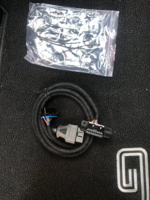
This is my Dummy OBD Relocation harness that fits 05-14 Mustang that installs a dummy OBDII port in OEM location then allows relocation of real OBDII port elsewhere........I'm gonna relocate mine to the passenger side just under the glove box to allow hookup of my laptop to OBDII port to allow VCM Scanner datalogging\Forscan datalogging & remote datalogging using my HPTuners MVPI2+ interface alone (since upgrade to Pro+ kit I can now download a VCM Scanner datalogging channel file into the MVPI2+ interface & either set it up to trigger recording off a trigger set in the interface code--such as engine RPM for example--or by manually pressing the BT button) w\o any interference of interface\dongle while driving car.

This allows a permanent mounting solution so that I don't have to rig up\rig down cabling keeping it clear of all other components (steering wheel, shifter, etc) while also offering some theft deterrence at the same time. The harness is made using OEM Ford wire conduit to "blend" into the wire looming underneath dash for stealthiness as well.

Will be recording datalogs soon now.................................

;)
 

GlassTop09

Senior Member
Joined
May 24, 2019
Posts
1,142
Reaction score
525
Location
Farmington, NM
Why do you need a dummy port?
I don't........never said I did need a dummy OBDII port.

I chose this part because it checked off all the boxes I wanted in a relocation harness: plug & play design, comes w\ OEM wire conduiting\protection already installed, is a "permanent" install--once in doesn't have to be touched\moved again (but can also be easily removed as well if desired w\o damaging any of the original wiring\OBDII socket\harness thus can be easily moved to another Ford vehicle as well thus future usage so a 1 time purchase), doesn't change\interfere w\ the interior design\layout thus looks "OEM" as it is fully hidden underneath dash (depending on where\how I choose to install the relocated OBDII socket on passenger side of car) & it allows me to datalog my car while driving it w\o chance of interfering w\ any OBDII interface's connection while it is plugged into the relocated OBDII port.

The dummy OBDII port is the extra that I don't need, but it also does serve a tangible purpose so is a welcome "extra". The price was within what I wanted to pay for it, so I bought it since it fulfills all my wants\needs.

To each their own.........
 

GlassTop09

Senior Member
Joined
May 24, 2019
Posts
1,142
Reaction score
525
Location
Farmington, NM
FYI..............................

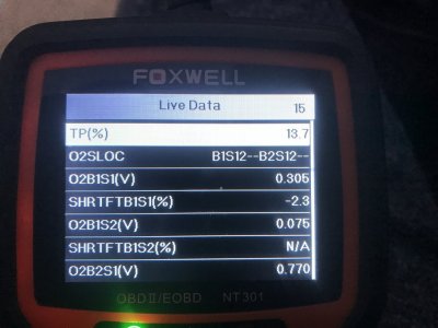
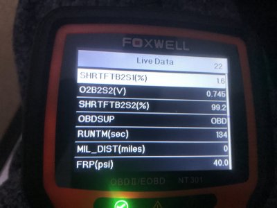
Thought I'd put this here for those interested so when you're looking at your scan tool's live data you know what this part of your screen's data is representing:
Scan Tool Live Data of Ford SO PCM running Catalyst CE Ratio Tests.JPG Scan Tool Live Data of Ford SO PCM running Catalyst CE Ratio Tests (2).JPG
These 2 pictures are showing the section of live data of the 2 front NB O2 sensor's (O2B1S1\O2B2S2) voltage reactions to PCM swinging the fueling to switch the O2 sensors........this reps Lambda 1.0 (if fuel stoich AFR setting in tune matches the actual fuel's stoich AFR that is burned in engine). The PCM is measuring the amplitude range of these 2 front O2 sensors (the distance between the lowest to highest voltage swing) as this tells the PCM exactly how much free O2% from amplitude swing length & time spent below the 450mV cross current line (to test the cat's cerium O2 storage capacity) & how much fuel it sent into the cats from amplitude swing length & time spent above the 450 mV cross current line (to test the cat substrate's ability to oxidize the fuel using the stored free O2% into CO2 & H2O), then it looks at the 2 rear NB O2 sensor's (O2B1S2\O2B2S2) voltage amplitude & RTL\LTR V\ms transition time reactions that drop below the 450mV cross current line only relative to the 2 front NB O2 sensor's voltage switching amplitude rates in 3 different cells at 3 different switching count totals (1-50 counts, 1-70 counts, 1-30 counts) rep'ing various engine RPM, load%, ECT, STFT+LTFT (as measured thru the SHRTFTB1S1%\SHRFTB2S1% PIDs), MPH, cat operating temps, etc then compared to the 2 rear O2 sensor's SHRFTB1S2%\SHRFTB2S2% to come up w\ the Cat CE Ratio result of cats ability to store\use up the free amount of measured free O2% the PCM sent into the cats to then test their efficiency against the max CE ratio threshold limits for passing\failing result. The PCM can adjust the amount of free O2% it sends into the cats by simply readjusting the front O2 sensor's amplitude switching range narrower\broader based on need.....within the max amplitude range design of the O2 sensors being used. For Ford this is either the NGK spec or the Bosch spec (NGK spec was in use when these 05-10 S197's were built thus the PCM's OEM O2 sensor CL controls were factory tuned to this spec.......).

None of this has any effect on an engine's HP\TQ output capabilities as the engine's AFR is controlled WITHIN the avg switching rates measured in the center of the switching around the 450mV cross current line of the front NB O2 sensors for Lambda 1.0, not the outer extremes......where the PCM is managing\monitoring the cat's operations\efficiency from thus has NO EFFECT on engine HP\TQ output concerning AFR.

Those Ford engineers are some very smart folks indeed!

So, this SO PCM, when all the supporting tune settings & components are set up & operating correctly (MAF Adaption, fuel stoich AFR, O2 Transport Delay tables, PCM operating in CL Normal Mode--which uses the fuel stoich AFR tune setting only as the "CL fuel map" thru EQ Ratio Lambda 1.0 formula--, properly operating front\rear NB O2 sensors for accurate O2 feedback data, properly tested\operating EVAP system--only area where unmetered fuel & air is entering the induction system by design so PCM is monitoring this during the EVAP purge cycle, rest of induction side components are free of vacuum leaks, the Spark Advance\Base\Cold & Emissions Reduction mapping's OEM settings are left intact, etc), the PCM can usually manage the cats operational health & keep them operating efficiently. So, a NA 4.6L engine should be able to maintain & pass an emissions cert test, regardless of the CAI, TB, cams, LTH's or cats used (as long as the cats are a TWC OBDII design--HC, CO, NOx & OBDII designed meaning the cats have cerium put in the substrates along w\ the other precious metals to store\release the free O2 from PCM switching of the front O2 sensors---a necessity to operate under OBDII monitoring) from a position of controlling the exhaust "AFR" sent into the cats to maintain max cat efficiency.

So pay attention to the live data SHRTFTB1S1%\SHRTFTB2S1% switching amounts when you're looking at the O2 sensor's live voltage data thru your scan tool.......if they are exceeding -2.3%\2.3% & you're getting P0420\P0430 DTC's.....it's not necessarily the cats failing.......they may be getting overrun w\ excess O2% that is outside of the PCM's ability to control it.........then you'll have to track it down, ID the failing component(s) & fix it 1st to then clear\rerun OBDII cat monitors to determine if the cats have actually failed or not before replacing them. The 1st item that can affect this SHRTFT is the EVAP system (unmetered fuel\air entry into IM during purge cycle or CPV failure......PCM uses STFT readings below\above the established engine baseline STFT readings during non-purge cycles while performing purge cycles to determine if EVAP canister is empty thus is trying to account for the unaccounted unmetered fuel vapors\air entry from purging the EVAP canister into the engine's overall AFR control so is critical that no air leaks exist in any lines between fuel tank, EVAP canister & engine IM, no air leaks in any other part(s) of the induction system\exhaust system around the O2 sensors & CPV is leak free when it closes & PCM has good metering control of EVAP flow into IM while the CPV is commanded open so the SHRTFTB1S1%\SHRTFTB2S1% readings are held as close to 0% as possible).

An IM's EVAP port routing design into its plenum can also affect this in a negative way by causing uneven EVAP distribution into the IM plenum\intake runners causing excessively uneven AFR in the individual cylinders on a bank which can throw off the PCM's EVAP purge control thru erratic\uneven O2 sensor feedback causing erratic STFT readouts causing the EVAP system to be over purged causing erroneous cat "CE ratio threshold P0420\P0430 DTC failures" as well as burnt spark plugs from the excessive air\fuel leanout........ask me how I know this..........all info is recorded in this thread.

The only time a cat should get into trouble treating exhaust is from sheer exhaust airmass volume overloading the cat substrate's ability to treat said airmass. This is tied to the engine's load%\VE output only thus the cat's SIZE measured in GVWR (the other reason for the GVWR rating on the VEI sticker in door jamb--for cat min sizing per OEM vehicle as factory MY manufactured) is the critical issue.

So, the only time a 4.6L engine should have potential issues physically passing an emissions cert test is when it is equipped w\ FI which is increasing\ can increase the engine's load%\VE output to exceed an OEM or some aftermarket cat's capacity to treat the increased amount of exhaust HC, CO & NOx in the airmass under the threshold limits, thus w\ FI it will be according to the amount of boost being used AND the physical SIZE of the cats in use--along w\ the other items mentioned in the prior paragraph(s) above that will determine the success\failure of this. So, a larger sized cat(s) is needed to handle the extra exhaust airmass volume from any load%\VE increase in excess of the vehicle's GVWR (how aftermarket cats are sized.......airmass thus exhaust is measured in lbs\min or gms\mi....there are larger GVWR-sized cats available) based off the engine's NA displacement max load%\VE output @ SL & max RPM's. The only other factor concerning FI will be the sheer amount of extra HEAT generated in the exhaust--can easily exceed 1,600*F-1,800*F or higher--that can simply destroy a cat's substrate as the majority are rated to a max of 1,500*F.....even a metal substrate if subjected to this extreme heat output over time, thus will require a cat designed for this (such as G-Sport\GESI UHO cats......they're now rated to handle up to as much as 1,200 HP\2,700*F & are Fed OBDII-cert legal....not CARB OBDII).

That is.......if being EPA legal is desired while driving said modded vehicle on Fed roads\hiways...........
 

Latest posts

Support us!

Support Us - Become A Supporting Member Today!

Click Here For Details

Sponsor Links

Banner image
Back
Top