Lunati VooDoo #21270700 Camshafts

GlassTop09

Senior Member
Joined
May 24, 2019
Posts
1,145
Reaction score
526
Location
Farmington, NM
WOW I have never heard of a tuner surreptitiously disabling the Knock sensors!

What is your A/F ratio?
Hi JC SSP,
Well, all I can say is.......the HPTuners VCM Scanner datalog (which is reading the tune file settings out of PCM) & tune file don't lie..........so there are some tuners out there that do this kind of stuff covertly. If it weren't for the fact that I have the means to "look under the hood" so to speak, I wouldn't have known either..........

So be thus advised................they do exist.

Now as for the A\F ratio........A\F ratio at what point? I'll assume that you're referring to WOT here..........

I can't say specifically at this time as I don't have my Zeitronics Dual WB Controller installed yet to use WB's during WOT to verify the actual A\F ratio actually being applied while the knock sensors were off in my prior tuner's tune.......I DO know he used a WB to set all this while on the dyno (I personally saw the WB controller display showing 14.64 AFR......which means nothing except the WB was reading actual Lambda 1.0 at the in-tune EQ Ratio Lambda 1.0 setting using Lambda .85\.87 in OL base fuel map when EQ Ratio Lambda 1.0 equation in his tune file was using a fuel stoich AFR setting of 14.64 (which is wrong for the E10 unleaded 91oct fuel the engine was burning during all tuning......this is actually between 14.08 to 14.13 for E10) but from this info I can only deduce that the actual A\F ratio matching the calibrated WB's Lambda 1.0 reading being used was between 12.444 AFR @ .85 Lambda\ 12.736 AFR @ .87 Lambda.....(actual Lambda reading w\ correct 14.08 fuel stoich AFR for E10 fuel in EQ Ratio Lambda 1.0 equation at same 12.444 AFR is .88 Lambda\at same 12.736 AFR is .90 Lambda) which isn't bad & as long as nothing unforeseen occurred to cause this AFR to lean out any more than this (this is the Russian roulette I'm referring to) then you can potentially get away with doing stuff like shutting off knock sensors at WOT..........the problem w\ doing this kind of stuff is that this should NEVER be the TUNER'S decision\right ALONE to make w\ a CUSTOMER's vehicle w\o CUSTOMER's knowledge of, thus CUSTOMER's CONSENT......BEFORE APPLICATION of this kind of bass-ackward tuning to "band-aid" a physical component issue.......especially a SAFETY component!

So if the CUSTOMER is left in the dark & doesn't know this kind of stuff is being done w\o their knowledge\consent AND customer goes out & blows his\her engine up......say due to a simple EVAP CPV failure causing excess air entry into engine while under WOT loads........was the cause of engine blowup the EVAP CPV failure?........or the bass-ackward tuning band-aid tuner put in PCM tune file that set the engine up for failure from a simple unrelated part failure that, if the knock sensors were not by-passed AND were working properly would have potentially protected\saved engine from self-destruction.........the reason WHY they're provided on the engine in the 1st place?

The real problem now becomes an issue of he said, she said.......CUSTOMER can't PROVE any of this w\o accessing the tune file & finding the altered tuning\datalog showing the results of this altered tuning that set up this failure scenario, but TUNER CAN SAY w\ some truth that the cause was the bad EVAP CPV......but inside he\she KNOWS it was THEIR fault since THEY disabled the 1 safety device--w\o customer permission--that could've prevented this.
The question now becomes...........how HONEST will the TUNER be & eat a potential $3,000-$20,000+ engine replacement when they KNOW at this juncture that YOU the CUSTOMER can't PROVE it was THEIR doing thus THEIR fault?

So, in the end, its usually the CUSTOMER who is getting the SHAFT..........on both ends.......instead of the TUNER who SHOULD BE.

There's a whole lot more of this kind of stuff going on behind folk's backs in this industry that most aren't fully aware of...............also from folks you may be entrusting to..................

The only way I found all this out w\ my own car was from just 1 day deciding to start doing my own tuning & I got a thought much later on to reload prior tuner's tune file then datalog (just recently relocated my car's OBDII port to passenger side so I can run driving datalogs w\o OBDII interface connection interference from clutch operations) it to use to back-check some issues that I was seeing w\ my knock sensor activity thru datalogs of my own tune file's tuning to see if the issue was my tuning or the knock sensors themselves, since I couldn't find any reasoning tuning-wise on my end for what I was seeing w\ my tune file loaded so I assumed my prior tuner's tuning was done properly......even though I've found\corrected several other tuning mistakes prior this 1 in my copy of his tune file....and it was in the PCM prior my tuning start w\ no known issues concerning knock........as Paul Harvey would say......"wait until you hear the rest of the story".

In my case, just insert the word "see" for "hear". This is from a person who has been doing tuning for 25+ years & specializes in Ford tuning (he owns 2--a '07 GT & a '07 GT500 & races both regularly) .......so I trusted his expertise............nice guy to boot as well.

Now I have the recorded proof\evidence in hand to bolster all that I've typed in here...........

I just was blessed to catch yet another break from future potential catastrophic engine failure..............

My 2 cents.......................
 

JC SSP

Senior Member
Joined
Nov 8, 2022
Posts
1,078
Reaction score
466
Location
FL
Very interesting... This is a very in-depth when it comes to the specific tuning parameters.

In the early days, I always relied on "canned" tune since most of the reviews and comments were positive (i.e., Hypertech chips-E-proms, or SCT strategy tunes).

On the more recent custom tunes.... talking with the tuner and completely filling out the Mods/set-up form and/or interacting with the team at the shop and other customers on their feedback and experience.

Like everything in life, trust but verify.
 

GlassTop09

Senior Member
Joined
May 24, 2019
Posts
1,145
Reaction score
526
Location
Farmington, NM
FYI.....................(warning, long posting)

Just remembered a few things that I observed before taking a break waiting on parts\holidays that made a difference thus IMHO worth mentioning..........

1.) I did actually test the '09 GT OEM knock cyl threshold sensitivity map settings in my tune file against the badly spiking knock sensors........was surprised to find that the Ford-tuned OEM cyl knock sensitivity threshold mapping actually did a much, much better job at KS signal interpretation than the detuned mapping that either prior tuner or BAMA tuners used.......w\ these 14yr old wore out KS's currently being used. Good enough that I was able to squeeze in 1* more spark advance timing across the base BKT spark advance map & 1.5* more spark advance timing across the base MBT spark advance map w\ less overall KS added spark advance timing being pulled......they also did a much better job of exposing the bad KS #1 signal spikes (showing knock on REDUCING KS voltage signal spikes instead of increasing voltage signal spikes).
So, all these results validates Jeff Evans Ford Mod Motor training concerning this knock sensor mapping.......unless you're running a built engine using forged components\aggressive camshaft profiles that require valve spring changes (clearance\noise frequency differences from NA SBE) or FI application due to increased cyl pressure use above NA SBE thus noisier, you don't need to mess w\ any of the Ford-tuned OEM knock sensor settings period as all this is already tuned to a NA SBE engine, even when running fairly aggressive camshafts on it (most NA camshafts most folks run use more duration w\ valve lift in the .450" range which is close to OEM lift thus use the same stock valve springs so valve train noise is very similar to OEM cams) so as long as no exhaust is physically hitting\excessively vibrating causing false KS signal generation you should be good & can trust the results........unless the KS's themselves are going bad.......why I data log both KS #1\#2 mic-generated voltage signal outputs along w\ the individual PCM generated per cyl knock add\subtract outputs to verify 1 against the other.....

2.) Even though I don't have my WB's installed yet, I DO graph the PCM STFT+LTFT combined NB O2 sensor outputs during CL operations.....which clearly show the A\F signaling running between -1% to 1% w\ several 0% recorded in between (this is done comparing the MAF sensor voltage output after smoothing is applied against the front NB O2 sensor output voltages.....so a true front end airmass to back end airmass measurement comparison) pretty much across the running graph except when PCM goes into injector throttle cut (transient's decel gain richens air\fuel during deceleration\enleanment to maintain engine stability so shows up as -1% in the graph cells.....using Lambda 1.05 off EQ Ratio Lambda 1.0 A\F control) & during actual OL cold starts (shows the PCM enrichened OL fueling to account for wall wetting due to cold airmass interference w\ fuel\air atomization until engine warms up......mostly in the -3% to -1% range as referenced to the MAF read airmass during cold starts since the NB O2 sensors aren't online yet). In CL the B1\B2 front NB O2 sensors LTFT's w\ STFT's switching normally when engine running under load are between -0.8% thru 0.8% w\ several 0.0% in between......this validates the MAF table tuning & LWFM table tuning (actual airmass at reference 78%\21% air density\composition), MAF Adaption, all SD map tuning, loaded fuel injector data in tune file & injector operations, the 14.08\14.13 fuel stoich AFR setting being used in the PCM EQ Ratio Lambda 1.0 A\F control formula equation matching the E10 91 oct unleaded pump gas being burned in engine AND the accuracy of the NTK 22060 front NB O2 sensors voltage outputs (as generated off same reference 78%\21% air density\composition in NB O2 sensor reference air chambers they were calibrated to.......that MAF sensor is also measuring thru its slot) as being dead on accurate thus, in theory, I could just simply set the base OL fuel map's Lambda settings to the desired Lambda A\F ratios for WOT operations since this map is telling the same PCM EQ Ratio Lambda 1.0 A\F control formula using the same fuel stoich AFR setting for the same E10 91 oct unleaded fuel being burned in OL as well as in CL what WOT A\F amount in Lambda to apply then use the knock sensors & spark timing to dial it all in............as long as the car's fuel system can actually DELIVER the necessary fuel mass to match up to the PCM Lambda control......which is the $64 question & why you need a calibrated WB A\F sensor during OL-PE to mostly verify the fuel delivery side......since this SO PCM disables the front NB O2 sensors during OL-PE Demand by default (this CAN be set up in tune file so that the PCM actually stays in CL during OL-PE Demand as well thus enables the front NB O2 sensors to monitor STFT+LTFT during OL-PE Demand\WOT......but it won't be accurate due to the design of NB O2 sensors only being able to be accurate in a narrow range window......FYI for those so interested).

So, the A\F control side of my tune file run in PCM as is currently set up according to VCM Scanner datalog data is pretty much spot on accurate so I can trust it.

This is how the OG tuners back in the day did WOT tuning before the advent of WB O2 sensors (or sometimes called A\F sensors since they can actually METER the read exhaust O2% content against the reference Lambda 1.0 airmass O2 stoich% value they're calibrated to inside their ref chambers, thus can accurately interpret the fuel side of the A\F ratio across a wide range to come up w\ the accurate A\F ratio being used in engine usually read out in Lambda then a WB controller will rescale the Lambda reading referencing it accordingly to a known A\F stoich--like 14.7\1--display in controller window).

3.) The resetting of the injector ref CA setting in tune to match the adv dur cam IVO point of my Lunati cams (to replicate the OEM Ford fuel injection tuning intention as w\ stock cams in accordance w\ VCT operations), along w\ resetting all of the tune file's mapping\settings that affect engine cold starts\catalyst controls back to stock '09 OEM Ford tune settings really corrected all of this using these non-stock Lunati camshafts. Have tested all this several times recently from a reflash in early morning sessions (to intentionally clear all KAM so PCM is only using the raw settings in tune file w\o any assist from learned KAM data to test cold start performance in actual cold conditions) in my engine at AAT's as low as 11*F thus far.......engine starts up immediately w\o any stumbling or misfiring thruout the cold start period, follows the ECT cold start idle map RPM\spark timing settings to the number w\o excessive flaring of cold engine RPM's & no black\blue smoke emitted from exhaust at all......smooth as glass & sounding very good.
This injector ref CA setting is shown to be very important for proper engine cold starts as well as proper fuel atomization\swirl into combustion chambers for optimum engine A\F mix\combustion thruout......regardless of camshaft profile being used so needs to be set properly to line up the PCM fuel injection EOIT control to the camshaft's adv dur IVO timing point in CA degrees so when VCT is applied the PCM can always maintain this relationship properly across all engine RPMs & VCT cam retard\advance operations.

Posted for informational purposes. Accel pedal assembly & knock sensor harnesses should all get here by Thursday according to product delivery tracking............

Happy Holidays to all!
 
Last edited:

GlassTop09

Senior Member
Joined
May 24, 2019
Posts
1,145
Reaction score
526
Location
Farmington, NM
Is there a difference between the GT500 pedal and the “regular “ pedal other than the medal cover?
Good question Laga................so I just checked Rock Auto site given part# for this APP across both a '09 GT & '09 GT500 & the results show the exact same part# for both vehicles.

So, from this data, it appears that they both use the same physical APP pedal sensor assembly.......just the OEM GT500 unit comes w\ the metal pedal cover whereas the OEM GT unit does not........so Rock Auto offers it under both GT & GT500........

I wasn't aware of this at the time, so I thought that Standard Products was offering a modified version of the OEM GT unit w\ the GT500's metal cover............

This I DO know.........if you buy this thru Ford dealership, you'll be paying at minimum 2x this price.........that was for the GT unit w\o the metal GT500 cover!

Hope this helps.
 

GlassTop09

Senior Member
Joined
May 24, 2019
Posts
1,145
Reaction score
526
Location
Farmington, NM
The big discovery that I found was that, even though prior tuner had the knock retard max advance map settings from .10 load thru .50 load & from 500 RPM's thru 5,000 RPM's set at 8* advance, the PCM would NOT ADVANCE the spark timing past the base MBT\MBT VCT combined spark advance setting graph line from the base BKT\BKT VCT spark advance setting graph line when the base BKT was set LOWER than the base MBT less than the 8* knock max spark advance setting (area where the PCM will apply additional knock advance spark timing to the base BKT\BKT VCT combined spark advance timing only), but will apply it up to the MBT\MBT VCT timing graph line itself then stop so the combined BKT\BKT VCT\knock max advance timing NEVER crossed the MBT\MBT VCT combined spark timing graph line, even if the knock max advance spark map settings exceeded the BKT\MBT gap difference.......so the PCM IS CODED TO NOT CROSS THIS POINT ITSELF......if the BKT isn't INTENTIONALLY set up in tune file to be higher than the MBT! This wasn't taught in Jeff Evans HPTuners Ford Mod Motor tuning training videos or mentioned on any tuning site or on HPTuners forums (that I looked thru) at all.............
FYI............................

I ran this by Jeffery Evans @ Evans Performance Academy (who I purchased access to his 05-10 HPTuners Ford Mod Motor tuning training course) & he replied that he knew there were some of these factory SO PCM's in the later MY's (he didn't say which ones but from all that I've seen this must be from '08 thru '10 MY's) have a more enhanced calibration in them that will do the things I've witnessed mine ('09 GT) doing. Since this is so, he doesn't elaborate on these differences in his base training course (includes the boutique calibrations from folks like Roush & Shelby) to keep his training focused on a simple to follow tuning methodology that is repeatable.........so I know now that my PCM has this more enhanced calibration\strategy loaded in it...........it works very, very well at maintaining engine at optimum HP\TQ across the entire engine operational envelope when it is properly set up & used to its strengths.

PS---Jeffery explained it as the BKT is the "floor" & the MBT is the "ceiling" w\ the knock sensor spark advance as the "ladder" to climb up\down between the 2 when the BKT & MBT spark advance maps are physically separated w\ the BKT being lower than the MBT, so the PCM will always be looking to climb the ladder from BKT to MBT whenever the knock sensors are active & no knock is detected, but if some knock is detected, as long as the pulled knock spark timing doesn't try to go below the "floor" (BKT), it is only running here due to this momentary situation (PCM is taking a break & cleaning the paint brush). Then when the knock sensors detect no more knock, the PCM will start climbing back up the ladder again to try to continue painting the "ceiling" (MBT) automatically & since this is the ceiling, the PCM will not try to paint past the ceiling......the highest point in the room, so to speak.....regardless if the knock sensor max advance map settings say the PCM can go to the "roof".............

A much better way of explaining this PCM action..........................

Posted for informational purposes.
 
Last edited:

DieHarder

Senior Member
Joined
Nov 9, 2019
Posts
1,467
Reaction score
758
FYI.....................(warning, long posting)

Just remembered a few things that I observed before taking a break waiting on parts\holidays that made a difference thus IMHO worth mentioning..........

1.) I did actually test the '09 GT OEM knock cyl threshold sensitivity map settings in my tune file against the badly spiking knock sensors........was surprised to find that the Ford-tuned OEM cyl knock sensitivity threshold mapping actually did a much, much better job at KS signal interpretation than the detuned mapping that either prior tuner or BAMA tuners used.......w\ these 14yr old wore out KS's currently being used. Good enough that I was able to squeeze in 1* more spark advance timing across the base BKT spark advance map & 1.5* more spark advance timing across the base MBT spark advance map w\ less overall KS added spark advance timing being pulled......they also did a much better job of exposing the bad KS #1 signal spikes (showing knock on REDUCING KS voltage signal spikes instead of increasing voltage signal spikes).
So, all these results validates Jeff Evans Ford Mod Motor training concerning this knock sensor mapping.......unless you're running a built engine using forged components\aggressive camshaft profiles that require valve spring changes (clearance\noise frequency differences from NA SBE) or FI application due to increased cyl pressure use above NA SBE thus noisier, you don't need to mess w\ any of the Ford-tuned OEM knock sensor settings period as all this is already tuned to a NA SBE engine, even when running fairly aggressive camshafts on it (most NA camshafts most folks run use more duration w\ valve lift in the .450" range which is close to OEM lift thus use the same stock valve springs so valve train noise is very similar to OEM cams) so as long as no exhaust is physically hitting\excessively vibrating causing false KS signal generation you should be good & can trust the results........unless the KS's themselves are going bad.......why I data log both KS #1\#2 mic-generated voltage signal outputs along w\ the individual PCM generated per cyl knock add\subtract outputs to verify 1 against the other.....

2.) Even though I don't have my WB's installed yet, I DO graph the PCM STFT+LTFT combined NB O2 sensor outputs during CL operations.....which clearly show the A\F signaling running between -1% to 1% w\ several 0% recorded in between (this is done comparing the MAF sensor voltage output after smoothing is applied against the front NB O2 sensor output voltages.....so a true front end airmass to back end airmass measurement comparison) pretty much across the running graph except when PCM goes into injector throttle cut (transient's decel gain richens air\fuel during deceleration\enleanment to maintain engine stability so shows up as -1% in the graph cells.....using Lambda 1.05 off EQ Ratio Lambda 1.0 A\F control) & during actual OL cold starts (shows the PCM enrichened OL fueling to account for wall wetting due to cold airmass interference w\ fuel\air atomization until engine warms up......mostly in the -3% to -1% range as referenced to the MAF read airmass during cold starts since the NB O2 sensors aren't online yet). In CL the B1\B2 front NB O2 sensors LTFT's w\ STFT's switching normally when engine running under load are between -0.8% thru 0.8% w\ several 0.0% in between......this validates the MAF table tuning & LWFM table tuning (actual airmass at reference 78%\21% air density\composition), MAF Adaption, all SD map tuning, loaded fuel injector data in tune file & injector operations, the 14.08\14.13 fuel stoich AFR setting being used in the PCM EQ Ratio Lambda 1.0 A\F control formula equation matching the E10 91 oct unleaded pump gas being burned in engine AND the accuracy of the NTK 22060 front NB O2 sensors voltage outputs (as generated off same reference 78%\21% air density\composition in NB O2 sensor reference air chambers they were calibrated to.......that MAF sensor is also measuring thru its slot) as being dead on accurate thus, in theory, I could just simply set the base OL fuel map's Lambda settings to the desired Lambda A\F ratios for WOT operations since this map is telling the same PCM EQ Ratio Lambda 1.0 A\F control formula using the same fuel stoich AFR setting for the same E10 91 oct unleaded fuel being burned in OL as well as in CL what WOT A\F amount in Lambda to apply then use the knock sensors & spark timing to dial it all in............as long as the car's fuel system can actually DELIVER the necessary fuel mass to match up to the PCM Lambda control......which is the $64 question & why you need a calibrated WB A\F sensor during OL-PE to mostly verify the fuel delivery side......since this SO PCM disables the front NB O2 sensors during OL-PE Demand by default (this CAN be set up in tune file so that the PCM actually stays in CL during OL-PE Demand as well thus enables the front NB O2 sensors to monitor STFT+LTFT during OL-PE Demand\WOT......but it won't be accurate due to the design of NB O2 sensors only being able to be accurate in a narrow range window......FYI for those so interested).

So, the A\F control side of my tune file run in PCM as is currently set up according to VCM Scanner datalog data is pretty much spot on accurate so I can trust it.

This is how the OG tuners back in the day did WOT tuning before the advent of WB O2 sensors (or sometimes called A\F sensors since they can actually METER the read exhaust O2% content against the reference Lambda 1.0 airmass O2 stoich% value they're calibrated to inside their ref chambers, thus can accurately interpret the fuel side of the A\F ratio across a wide range to come up w\ the accurate A\F ratio being used in engine usually read out in Lambda then a WB controller will rescale the Lambda reading referencing it accordingly to a known A\F stoich--like 14.7\1--display in controller window).

3.) The resetting of the injector ref CA setting in tune to match the adv dur cam IVO point of my Lunati cams (to replicate the OEM Ford fuel injection tuning intention as w\ stock cams in accordance w\ VCT operations), along w\ resetting all of the tune file's mapping\settings that affect engine cold starts\catalyst controls back to stock '09 OEM Ford tune settings really corrected all of this using these non-stock Lunati camshafts. Have tested all this several times recently from a reflash in early morning sessions (to intentionally clear all KAM so PCM is only using the raw settings in tune file w\o any assist from learned KAM data to test cold start performance in actual cold conditions) in my engine at AAT's as low as 11*F thus far.......engine starts up immediately w\o any stumbling or misfiring thruout the cold start period, follows the ECT cold start idle map RPM\spark timing settings to the number w\o excessive flaring of cold engine RPM's & no black\blue smoke emitted from exhaust at all......smooth as glass & sounding very good.
This injector ref CA setting is shown to be very important for proper engine cold starts as well as proper fuel atomization\swirl into combustion chambers for optimum engine A\F mix\combustion thruout......regardless of camshaft profile being used so needs to be set properly to line up the PCM fuel injection EOIT control to the camshaft's adv dur IVO timing point in CA degrees so when VCT is applied the PCM can always maintain this relationship properly across all engine RPMs & VCT cam retard\advance operations.

Posted for informational purposes. Accel pedal assembly & knock sensor harnesses should all get here by Thursday according to product delivery tracking............

Happy Holidays to all!

Hmmmmm....maybe you should consider a side hustle "tuning" member's cars when Lito retires or start now if you like. :snoopy
 

GlassTop09

Senior Member
Joined
May 24, 2019
Posts
1,145
Reaction score
526
Location
Farmington, NM
FYI...................

Got car serviced this morning (6 month, 5,000 mi Ford-recommended oil service change interval using their MC 5W-30 Full Synthetic motor oil) & drove her around a little, then parked her & pulled Mode 6 data as follows:
B1 @ .117 idle LTFT @ -1.6%
B2 @ .148 idle LTFT @ 1.6%
CMBT @ 1,249*F
Data is clearly showing this engine's operations is getting better & better each DC since discovering\setting up this enhanced PCM calibration's capabilities concerning automatic, self-adjusting\optimizing spark advance timing application on the fly using knock sensor activity when base BKT spark map settings & base MBT spark map settings are physically separated at least 4* apart w\ the MBT being the highest point "ceiling" & BKT being the lowest point "floor" w\ knock sensor-applied spark advance timing being the "ladder" between the 2 maps, then using the BKT\MBT VCT Spark Advance Adder map multi settings applied thru PCM VCT operations to further enhance both the BKT & MBT spark advance maps (thus enhances TQ Management application of TQ calcs for PCM to apply) while making up for retarded cam IVC static compression loss when VCT retards cam EVO timing to increase power stroke TQ output.

I'm sure glad I stumbled into this finding.................that's for sure.
 

GlassTop09

Senior Member
Joined
May 24, 2019
Posts
1,145
Reaction score
526
Location
Farmington, NM
FYI............................

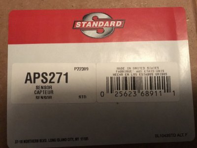
Got the accelerator pedal sensor today. This is the Standard part# that was on the box:
IMG_0658.JPG
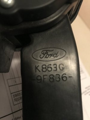
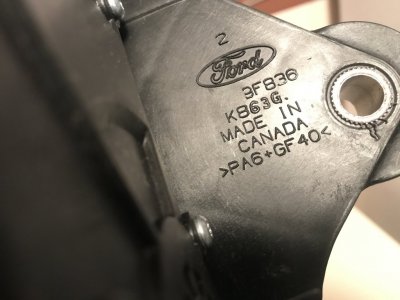
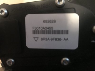
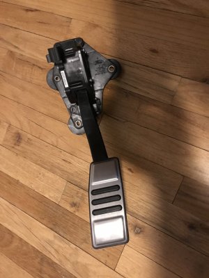
But this is what I pulled out of the Standard box:
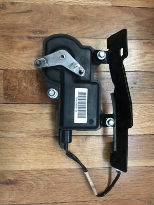
IMG_0660.JPG IMG_0661.JPG IMG_0659.JPG IMG_0662.JPG
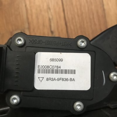
This is the genuine FoMoCo part# 8R3A-9F836-AA accelerator pedal sensor assembly for a 07-10 GT500.......that came in a Standard Products box.

Appears that Ford is clearing out their warehouses of older MY surplus S197 parts as I ran this part# thru 2 online Ford dealership stores & both of them reported this part# was discontinued & gave a reference #4R3Z-9F836-BD part number to the std base accelerator pedal sensor assembly for all 05-10 4.0L, 4.6L & 5.4L Base, GT, Bullitt, Shelby GT, Shelby GT500 & Shelby GT500KR cars because as of now, the last 2014 MY S197's have exceeded Ford's vehicle chassis, powertrain and EPA-mandated emissions warranty periods & this is now its 10 yr mark (local Ford dealership folks had informed me that 10 yrs after a platform's production run has ended, Ford starts to divulge of all leftover inventory of the particular platform from their warehouses to make room for the new models parts that are under chassis, powertrain & emissions warranties.........) so factory parts may start getting even harder to find.

So, got lucky on this 1.
 

Laga

Senior Member
Joined
Aug 10, 2019
Posts
999
Reaction score
521
Location
Chicago
GlassTop09, Since you are getting a new pedal, maybe you might find this interesting. Ran across it the other day. Beware, It’s long,

https://mustangforums.com/forum/200...tle-response-mod-must-see.html?ispreloading=1

As you stated, parts are going to start to be hard to get for our cars. Whenever I pull something apart and expose parts, I tend to replace them proactively if they are not too expensive. Probably going to look into replacing my 18 year old gas pedal too!
 

GlassTop09

Senior Member
Joined
May 24, 2019
Posts
1,145
Reaction score
526
Location
Farmington, NM
GlassTop09, Since you are getting a new pedal, maybe you might find this interesting. Ran across it the other day. Beware, It’s long,

https://mustangforums.com/forum/200...tle-response-mod-must-see.html?ispreloading=1

As you stated, parts are going to start to be hard to get for our cars. Whenever I pull something apart and expose parts, I tend to replace them proactively if they are not too expensive. Probably going to look into replacing my 18 year old gas pedal too!
Hey thanks for posting the link!
Yeah, this is tempting but is not really practical IMHO........but since I do have a test subject now to tear into w\o fear of causing damage........I'll open up my old pedal & investigate. I've a hunch that Ford may have rectified this issue w\ the later MY vehicles (circa 2007 for this thread) & they also may have designed this intentionally into all acceleration pedal sensor assemblies for the std base & GT models......no one in this old posting that I read mentioned anything about this being an issue w\ a 07-up GT500...........

On that note, I'll find out soon enough.........................

I've always done as you also stated when it comes to pulling\exposing parts on used vehicles over the years.......it's always better to be proactive than reactive in the long run......99% of the time it will also be cost-effective thus CHEAPER cost of ownership as well. The back-end payout is where it's at for effective costs of ownership..........

My current actions concerning my accelerator pedal assembly replacement & upcoming knock sensor harness replacement demonstrates this approach...........once you see a train wreck coming, why you gonna wait for it to hit you to know it's GONNA hit you if you keep putting it off?

The smart thing to do is to do the research & find out if Ford has already put out any factory upgraded parts from TSB rectification(s)\failure root cause analysis\Ford SVT development to take advantage of them.........this only adds more value to your used vehicle as you're actually making it a BETTER vehicle than it was when originally bought. Tis why I always look to use the later MY S197 & Ford S197 SVT replacement parts on my '09 Glass Roof wherever I can as they'll most certainly be the better designed\sturdier factory replacement parts to use on any 05-09 S197 across the board.

You also tend to not have to be calling wreckers & being stranded on the side of the road near as much..........
 

GlassTop09

Senior Member
Joined
May 24, 2019
Posts
1,145
Reaction score
526
Location
Farmington, NM
FYI.........................

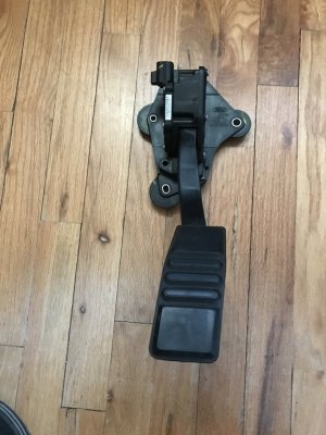
Here's a couple of pictures of my old pedal as I swapped them out 1st thing this morning................damn it was COLD outside!

IMG_0663.JPG IMG_0664.JPG
Here is the actual part# off this std GT accel pedal sensor assembly for reference..........this info verifies that I have an authentic FoMoCo 07-10 GT500\GT500KR accelerator pedal sensor assembly now installed in ole girl! PCM will automatically recalibrate to the new APP at-rest outputs upon initial KOEO after installation.

Now when the knock sensor harnesses get here, this is also gonna happen in the process of changing them:
IMG_0665.JPG
This is the old CMCV actuator\position sensor that I saved off my original stock '09 IM to reinstall onto this '08 IM I currently have to allow me to "reactivate" the CMCV's in the tune file so the PCM, when looked at thru a DAD in any future potential vehicle emissions certification tests getting implemented in my county, will look fully "OEM" w\ all items that are supposed to be enabled in the PCM enabled (no switches of any component\process in tune file set to disabled that weren't set this way in original tune file) & functioning as originally intended as seen thru the OBDII I\M Readiness & OBDII DTC function lists..........but still actually physically operating as all is currently set up.

In the tune file, all this IMRC system does is instruct the PCM to know when to switch from using all the IMRC Closed mapping to using all the IMRC Open mapping (and vice-versa) when the IMRC system actually opens\closes the CMCV's based off engine RPM & TPS% (engine load%) & report the CMCV position back to the PCM.....since all the IMRC Closed\Open maps in my tune file already have the same identical map settings loaded in all of them then this won't change anything currently set up tune-wise...........just stops the PCM from getting potentially "confused" as to which set of IMRC maps to use during operations (why all the IMRC Open map data is copied into all the IMRC Closed maps when CMCV's are removed......which you'd be doing anyway regardless)......since the PCM calibration code line arguments will be restored to normal.

So, in short, this move I'm doing now was really the "right thing" to have done when removing the CMCV's as this would have left the code in PCM set up as stock to "evade" a DAD check................that is, if you're still using an OEM stock IM.......

My plan was to reinstall this at the 1st opportunity I had when I had to pull the IM for any more important future reason for removal (like knock sensor replacement........). Once installed & revised tune file is loaded, then simply cycle thru KOEO after flash for PCM to recognize CMCV actuator then recalibrate\test it.

Already have the new revised tune file waiting..........(took a stock '09 tune file using the VCM Editor Compare feature & reset all the pertinent DTC's associated w\ IMRC operation in my current tune file that were set to "no error reported" when CMCV's were removed back to "MIL light" (except for the P2006 IMRC Stuck Closed B1\P2007 IMRC Stuck Closed B2 DTC's which were set to "No MIL light"---indicates that Ford was concerned to alert the driver only if these CMCV's hung OPEN which would have kept the PCM using all IMRC Open mapping......which was NOT set up for daily driving usage thus emissions, MPG & low RPM TQ output & engine idle IF PCM failed the MAF sensor to fall back on the IMRC Open LWFM table--stock IMRC Open LWFM table has 0 airload settings in the TPS 0% row cause this table was never intended to be used for daily driving--only for max HP\TQ engine power......they didn't care if the CMCV's got stuck CLOSED since the PCM would be stuck using all IMRC Closed mapping........thus stuck in daily driving status.........go figure).

My knock sensor harnesses are scheduled to arrive sometime today thru USPS.........we'll see.
 
Last edited:

dustindu4

Member
S197 Team Member
Joined
Aug 4, 2007
Posts
330
Reaction score
1
I’m always impressed by the depth of fine-tuning you do to your car. You’ve got the have the most dialed-in tune out there! Maybe one day I’ll find the time to learn all this stuff.. right now I barely have time to wash my car!
 

GlassTop09

Senior Member
Joined
May 24, 2019
Posts
1,145
Reaction score
526
Location
Farmington, NM
I've a hunch that Ford may have rectified this issue w\ the later MY vehicles (circa 2007 for this thread) & they also may have designed this intentionally into all acceleration pedal sensor assemblies for the std base & GT models......no one in this old posting that I read mentioned anything about this being an issue w\ a 07-up GT500...........

On that note, I'll find out soon enough.........................
The verdict is in.......................this APP is the REAL DEAL!!!!!
There's absolutely no flat spot(s) in this GT500\GT500KR APP off at-rest position pedal movement to engine response thru TB........I mean NONE. As I've found out from the 07-09 PowerStop GT500 OE Front Brake Replacement kit & now w\ this FoMoCo 07-10 GT500\GT500KR APP, I had to relearn to not rest my foot against the brake pedal\now the APP even slightly or I would FEEL the brakes start applying\HEAR & FEEL engine responding to very slight pedal movements that prior to replacing both parts I'd never feel\hear when resting my foot on either pedal........they're that responsive now.

IMHO if you're going to replace the '05-'10 base or GT APP for any reason, this FoMoCo part# 8R3A-9F836-AA '07-'10 GT500\GT500KR Accelerator Pedal Sensor IS the 1 to get..........if you can find them.

Hope this helps.
 

GlassTop09

Senior Member
Joined
May 24, 2019
Posts
1,145
Reaction score
526
Location
Farmington, NM
FYI..........................

Knock sensors came in today from LMR (Standard Products part# KS189).........so I got right on it due to the weather actually warmed up to a decent 45* w\ sunny skies so did it while the getting was good. Pulled all apart, swapped out the knock sensors (I applied a very thin coating of dielectric grease on block KS mounting bosses just as a precaution against any chance of future galvanic corrosion then installed bolts dry to not dampen any frequency exchange thru bolts into top of KS mics) & TQ'd them to 15 ft-lbs. Installed CMCV actuator\position sensor on IM & R&R'd from here.

Dabbed all electrical connector pins that I took apart w\ dielectric grease before reconnecting them to preserve\protect all connection integrity from corrosion (making this a habit to do to every electrical connection on car that I disturb going forward........) & cleaned all up after finishing job.

Hooked up laptop & flashed in tune revision #44 (same operational settings as last revision.....just reenabled IMRC actuator\position control, reloaded OEM IMRC Opening TQ% vs RPM map settings & reset all IMRC-related DTC's back to OEM settings so PCM can read\see\operate the CMCV actuator to tell itself when to switch from all IMRC Closed mapping to all IMRC Open mapping & vice-versa.......as explained in post #352) then started her up to start my full datalogging ritual after a tune flash. Checked over all work.......all good. Checked datalog after engine fully warmed up & idling at full hot idle temps.........all readings came back identical compared to last datalog thus all is sound (no leaks, no runs, no drips). Checked KS #1\#2 mic signal voltages.........both running very clean & steady in low-mid 70v range......approx 25v-30v lower avg signal generated voltage so noted.

Took car on same 37.6mi DC route......all looking good. Didn't do any rolling\stabbing WOT hits on this DC as I was just making a shake-down run to see how the new KS signals. 1st thing I noticed is how the car was running w\ better response all around, even though no operational settings were changed in tune file........so I'm assuming that this is due to reduced PCM overhead (assuming that when IMRC was disabled prior, PCM was actually excessively bouncing back\forth between the IMRC Open\Closed mapping trying to "figure out" which ones to use on rising\falling RPM & TPS%.......which is now rectified by using the CMCV actuator\position sensor w\ IMRC control reenabled in tune file & IMRC Opening TQ% vs RPM map settings giving guidance thus PCM is happy so not chasing between the IMRC Open\Close mapping willy-nilly so now is following the control settings which is instructing PCM to use IMRC Closed mapping exclusively until IMRC control tells PCM to switch to using the IMRC Open mapping once engine RPM's exceed 3,000 w\ TPS% above 52%........then return to IMRC Closed mapping when engine RPM's drop below 3,000 & TPS% drops below 52%---only plausible explanation I got thus may be just placebo effect)......

All ran excellent. All I\M Readiness monitors completed except EVAP as follows:
Cat CE Ratio results......
B1 @ .187.....idle LTFT @ -2.3%
B2 @ .176.....idle LTFT @ 1.6%
CMBT @ 1,328*F (noted cat operating temps were lower across the board.....highest operating temps never exceeded 1,525*F during this test).

All KS data came back clean except for the 1st 25*+ incline (about 3\4 mi winding uphill climb that I use to test engine under a low-speed (40-45 MPH) high load condition using 5th gear & setting engine load between .50-.60 load........started getting some very small, random knock spark timing pullback from running against the base MBT\MBT VCT spark advance tables (4.4* knock max spark advance timing above the base BKT\BKT VCT spark advance tables) but this time it is spread out more evenly between both banks so new KS's are making a difference......most cuts were less than 1* & lasted for approx 2-3 secs then went right back up against the base MBT\MBT VCT spark advance tables so it could just be exhaust piping excessively reverberating while under this much load causing the small knock (exhaust does have 2 hangers installed at trans crossmember......). When I did the same test on the 2nd 25*+ incline (this 1 is about 1\3 mi & straight) got all clean KS activity w\ knock max spark advance timing (4.4* above base BKT\BKT VCT spark advance tables) solidly pegged against base MBT\MBT VCT spark advance tables the entire time (the intentionally set 4.5* settings gap between all base BKT spark advance map settings & all base MBT spark advance map settings for PCM to add\subtract additional spark advance timing between the 2 based on knock sensor activity) so will check my exhaust hangers to see if some of the rubber in them is busted thus making metal contact......otherwise all is good.

I did have 1 pending DTC show up (P2015....Intake Manifold Runner Position Sensor\Switch Circuit Range\Perf. B1 .......hhhhmmmm, if I'm not mistaken, this is most likely due to PCM detecting this CMCV actuator either over rotating when energized to "open" the CMCV's (default CMCV actuator power off rest position is IMRC Closed) due to not being hooked up to actual CMCV butterfly shafts thus stops, PCM not seeing position return signal from CMCV actuator position sensor or just needing more cycle time for KOEO\continuous run time checks to realign the position signals........) so I'll see if this clears itself or sets a MIL.
Just got a thought.......gonna go into tune file & set the TPS% settings in IMRC Opening TQ% vs RPM map to 1.10% across all RPM's.......this should lock the CMCV actuator at default rest position thus PCM into using IMRC Closed mapping only.

Other than this little minor issue w\ IMRC, all is operating very well.

Have made some setting changes in next tune revision to both base BKT & base MBT spark advance maps (cut spark advance timing across .40 load row by 1.5*, across .50 load row by 2*, across .60 load row by 1.5* & .70 load row by 1* then applied smoothing to tie into rest of map settings to maintain my 4.5* spread between them.....to take a little out of this part of both base BKT & base MBT spark advance maps to lower cyl pressure a little in this operating area to see if this will clear up the small knock I saw while having engine under low speed, high load operation testing.

Headed down the home stretch to finish up now that APP & KSs are now rectified.
 
Last edited:

GlassTop09

Senior Member
Joined
May 24, 2019
Posts
1,145
Reaction score
526
Location
Farmington, NM
One more item I forgot to add in last posting...........

I also reset the ECT Min setting in the Misfire\Detection monitor in this flashed tune file revision from the 80*F setting we intentionally set some 3 yrs ago to stop the false misfire recording I started seeing after installing these Lunati VooDoo cams (engine not firing cyls smoothly off a cold start so would run up high cyl misfire counts & set P03xx DTC's until engine ECT exceeded 80*) back to the default 20*F to retest this since finding\resetting the fuel injector ref CA setting to match the Lunati cam's adv dur IVO timing point smoothed all this out.

So far, so good..............acid test will be when I do a cold start in early morning at very low AAT's then check the Mode 6 Misfire Monitor self-check data.
 

GlassTop09

Senior Member
Joined
May 24, 2019
Posts
1,145
Reaction score
526
Location
Farmington, NM
FYI..........................

Got up this morning to get all my cooking equipment setup & operational (homemade propane burner & 8 gal pot w\ basket to cook Cajun Broil for family\friends on Christmas Day) to find out the wife was going to meet her friends for breakfast........which gave me the opening to setup my laptop in my Stang & flash in the revised tune #45 (where I made the changes I discussed in post #355) then take her out on DC afterwards to test.........
Got all done & started car up while datalogging.......before starting car I left in KOEO for PCM to run thru system check on all sensors that can be checked w\o engine running......after approx 10 secs MIL light gave me the 4 flashes then turned off.......signaling that all passed KOEO self-check tests & engine is ready to start......this includes the CMCV actuator\position sensor so I know now that the P2015 DTC I got yesterday was from PCM continuous operation checks & not from PCM KOEO checks......which the 1.10% setting I entered across all RPM cells in the IMRC Opening TQ% vs RPM map should rectify this DTC (CMCV actuator will remain parked in default non-energized position to keep PCM using all IMRC Closed mapping--thus the CMCV position sensor should stay in alignment & PCM should pass it).

Took her on the same 37.6 mi DC route\routine & when I made the same 40-45 MPH low speed, .50-.60 high load test at the same 2 25*+ inclines, I got the exact same small, short, saw-toothed knock sensor output patterns---this time w\ PCM using 1.5*-2* LESS spark advance timing thru this engine load area in tune file---this is now pretty much confirming to me that this pattern is exhaust piping-related & not actual engine knock as only when engine is under this exact operating scenario is when this shows up.....nowhere else, even when engine loads are in the same .50-.70 range so I'm gonna dismiss this for now (got an idea on how I'm gonna rework my 2 exhaust hangers to eliminate any chance of getting metal-to-metal contact........future project).

Got all done, saved datalog then checked I\M Readiness thru VCM Scanner.......came back all completed except EVAP w\ NO pending DTC's.......all clean.......so the "CMCV issue" is now verified fixed!
Mode 6 Cat CE Ratio results as follows:
B1 @ .113.....idle LTFT @ -2.3%
B2 @ .113.....idle LTFT @ 1.6%
CMBT @ 1,399*F avg (hottest they got was 1,544*F.......this is telling me, along w\ the Cat CE Ratio results, that the cut spark advance timing from the middle of both the base BKT & base MBT spark advance timing tables is actually providing better engine combustion efficiency thus actually more HP\TQ along w\ better emissions so it's staying as currently set in tune file).

So, from this result, I'm calling my engine's tune file optimized in all other areas except full-on WOT (.80 thru 1.0 load)......have made the short WOT hits to get all WOT transition settings lined up to function properly\synched to where\how in tune file I want it all to happen so that I don't have this happening too early & interfering w\ normal CL-Normal Mode operations causing excessive fuel waste cycling PCM into\out of OL fueling but not fully transitioned into OL-PE Demand\WOT so still in CL........so she's now ready for full on WOT tuning.

This I might be better served to do on Hwy 550 S (4-lane divided smooth pavement w\ some very long & straight 3-4 mi stretches perfect for WOT tuning) instead of at NAPI International Speedway & Test facility (kinda rough, narrow 2-lane pavement that the farmers use to drag all their farming equipment to\from the produce\hay fields, so you know this pavement don't get too much attention as them farmers ain't so concerned about them tractors tramlining & hitting small potholes in the pavement).....but this will most certainly bring me in close proximity to catching a NM State trooper's attention at the wrong moment\time during a "tuning session"..........

Hope some of them are true gearheads....................
 

GlassTop09

Senior Member
Joined
May 24, 2019
Posts
1,145
Reaction score
526
Location
Farmington, NM
FYI........................(long posting)

1st off, here is provided the FoMoCo part# 1L2A-12A699-AA for the Bosch Siamese KS Paired Harness that fits all 05-10 S197 4.0L & 4.6L engines (got it off my 14 yr old worn-out OEM KS pair that I removed recently) for those who want to track these down.......good luck w\ that. Here is the Standard Motor Products part# KS189 for the same siamese KS paired harness (actual Standard Motor Products manuf'd part) that LMR carries. Checked Rock Auto w\ this SMP part# & they do not carry this part........only the single, square connector KS harness for all other MY Ford vehicles except the 05-10 S197 4.0L & 4.6L engines. So be advised.

Got on Amazon & found that Pypes makes a universal set of SS exhaust hangers that use a SS 2 1\2" exhaust pipe clamp w\ a 3\8" sleeve welded to 1 end of clamp for 8mm hanger rod to go thru & is adjustable. The 2 SS reinforced rubber-infused hangers are a bolt on part that will fit in the same area of trans crossmember that Ford used to install their factory exhaust hangers on the 05-06 GT's & the rubber inserts are replaceable, so I bought a full set of these to replace the ones I had local muffler shop install 4 yrs ago (that I believe is what is causing the small, infrequent, saw-toothed engine knock patterns when engine is put into a low RPM, high load scenario.......noted that the rubber insert is busted in hanger on B2 side (where most of this is coming thru) & also is starting to break up in hanger on B1 side (get very infrequent knock pattern thru this side but it does show) as the patterns just don't match up to a real engine knock pattern (looks too similar to a vibration pattern--like Morse code tapping signals--from exhaust piping transferring back into engine thru LTH's & these 2 hangers are the only part of exhaust that has a connection to unibody close to engine & exhaust proper fully clears unibody by a comfortable amount).
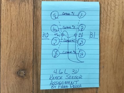
Will post back w\ results once I get these installed & datalog to test. Here is a drawing of the engine B1\B2 KS #0\#1 to cyl assignment I made according to firing order to use to ID which side of engine this exhaust vibration is mostly coming thru.........in my case, mostly thru B2:
IMG_0667.JPG

Since I've replaced my APP w\ this FoMoCo part# 8R3A-9F836-AA 07-10 GT500\GT500KR, I went in next tune revision #46 & reworked the TQ Management DD TQ Request map 16 thru 92 A\D count rows adding 2 lb-ft across 16 row (puts idle at 20 lb-ft, close to the 22.76 lb-ft I had tried some months back w\ old APP & had some idle control issues), 3 lb-ft across 42 A\D count row, 4 lb-ft across 65 A\D count row & 5 lb-ft across all rows from 92 A\D counts thru 545 A\D counts......did this to finish fine tuning drivability since I believe I've got all the spark advance mapping, VCT load% & spark advance adder mapping pretty well optimized from .10 load up thru .70 load in all tune mapping (only time it makes sense to touch this map) so only leaves .80 load thru 1.0 load in both BKT\MBT VCT Spark Adder maps to use to optimize full-on WOT (I don't think I'll need to mess w\ both base BKT\MBT spark advance map's .80 load thru 1.0 load rows at all since resetting the airload VCT load% map's VCT cam retard settings to use more EVO cam retard timing during WOT.......which also retarded the cam IVC timing the same amount--lowering dynamic cyl pressures--thus only need to adjust BKT\MBT VCT spark advance adder multi's to optimize total WOT spark advance timing thru VCT......we'll see). Also, for the last time, I'm resetting the Dynamic Airflow setting back to the default 10.90L (kept trying to see if lowering this would show any tangible benefits to accel transient fueling gains w\ this FP 62mm TB on initial TB opening ramps......results kept showing no difference\gains, even though all this was Ford-tuned\set up w\ the OEM 55mm TB......so I'm finally gonna put this back to OEM setting & walk away). I'm also using all 8 of the OEM Ford-tuned cyl KS sensitivity threshold map settings in tune file (been so since tune revision #43 so this is also back to OEM settings so engine is as protected as Ford could tune it to be......feel very good getting rid of the prior tuner\BAMA detuned KS sensitivity mapping.....even if it costs some max HP\TQ in the end).

Flashed this revision in early this morning (AAT @ 21*F) & started up to test Misfire Monitor operation thru cold start (had reset the ECT min enable setting back to the default 20*F from the 80*F we set after Lunati cam install to stop the false excessive misfire counts\P03xx DTC's during cold starts after resetting of the fuel injector ref CA EOIT setting to match the Lunati's cam adv dur IVO CA timing point which smoothed out all this). All went well & took car on same 37.6 mi DC route after reaching full hot idle temps.

All went like clockwork.......all Mode 6 I\M Readiness monitors completed except EVAP w\ no pending DTC's thus clean. Checked Mode 6 Misfire Monitor counts since misfire monitor was now active on cold start.......all last counts were low (#1 thru #4 cyls on B1 ea showed the same 21 counts & #5 thru #8 cyls on B2 showed between 8-13 counts) w\ all MM EWMA counts on all cyls showing 0's across the board--from cold start thruout DC--so this is also now rectified w\ the Lunati cams as well thus back to all OEM settings. The new APP showed no issues w\ the new TQ Management DD Request map idle 20 lb-ft TQ settings & drove excellent so am done messing w\ this mapping as well.

1 item of note concerning the CMCV actuator reinstall........this also reinstalled the main engine harness bracket that engine harness laid across & was attached to w\ it's X-Mas tree thus got it off the back side of engine block\trans bellhousing & secured it.......another plus for reinstalling this CMCV actuator\position sensor.

She's now very close to being fully tuned out to my satisfaction according to driving datalogs......once I get in WOT tuning, she'll be finished.

Been an excessively long process but also a VERY FULFILLING experience for me.........learned a LOT about these SO PCMs & their operations\coding that helped me out tremendously in setup\optimization.

Also got to shout out Jeffery Evans w\ Evans Performance Academy as his 05-10 HPTuners Ford Mod Motor tuning training course\course materials are IMHO worth every penny I spent & then some. His YouTube video format of his training course\materials is what makes his training unique & very easy to follow\learn.........as well as being a very sharp & well-versed tuner who is very easy to communicate with & is also very humble\comfortable w\ his knowledge & abilities.

A good source to go to if anyone else is looking to get into tuning their S197.................
 
Last edited:

Laga

Senior Member
Joined
Aug 10, 2019
Posts
999
Reaction score
521
Location
Chicago
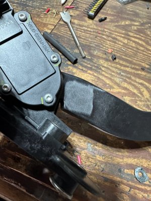
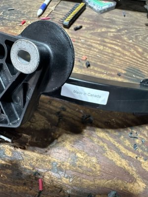
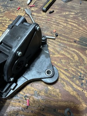
GlassTop09, after seeing you post on how your old APP was not performing to spec, I researched to see how to measure mine with Forscan. I haven’t had a chance to do it yet, but I did order a new APP through Amazon. The return center is 5 minutes from my house so I tend to order things in advance knowing they are easily returned. Anyway, it came today in a Standard box, model APS264. I all ready have the pedal cover that comes on the GT500 model. What I found interesting is that it appears that the Ford model numbers have been removed. There are marks in the same locations as yours where the numbers have been removed. Plus it has a Made in Canada sticker on it.
203D1626-6C6E-4A6E-A842-6ECC345AEB42.jpeg 04968426-A5A8-4AF7-A521-FFAE4691004F.jpeg AFB9475A-5F99-4E0B-A205-CB03F9B81D77.jpeg
 

GlassTop09

Senior Member
Joined
May 24, 2019
Posts
1,145
Reaction score
526
Location
Farmington, NM
GlassTop09, after seeing you post on how your old APP was not performing to spec, I researched to see how to measure mine with Forscan. I haven’t had a chance to do it yet, but I did order a new APP through Amazon. The return center is 5 minutes from my house so I tend to order things in advance knowing they are easily returned. Anyway, it came today in a Standard box, model APS264. I all ready have the pedal cover that comes on the GT500 model. What I found interesting is that it appears that the Ford model numbers have been removed. There are marks in the same locations as yours where the numbers have been removed. Plus it has a Made in Canada sticker on it.
View attachment 85007 View attachment 85008 View attachment 85009
HHhhmmmm.......I see that.

I checked the Amazon description of your SMP APS264 APP (Rock Auto shows the same SMP part# as well) & on the picture I could see the Ford oval was still on the pedal lever...........the part I found funny is that the Amazon description stated these were made in China..........while yours still has the "made in Canada" sticker label on it.

Well look at it this way............we know that Standard Motor Products has bought up a lot of this old Ford inventory. When I got the SMP KS189 knock sensor harnesses from LMR (I bought 2 sets to have a spare set on hand for future) since finding out that local Ford dealership couldn't find them in their parts inventory systems anymore, I was expecting to pull out a FoMoCo part# 1L2A-12A699-AA Bosch Paired KS harness out of the box........was surprised to find that SMP actually manuf'd these (assumption here), but got no complaints as they work damn good (draw good clean KS mic voltage signals w\ very little voltage variance between the 2 mics).

I also had the GT500 metal pad cover on my OEM APP (I removed it when I pulled it out) but since SMP was offering 1 w\ this GT500 metal pad already installed I went w\ it.

Just didn't know it would be an original FoMoCo part.............
 

Support us!

Support Us - Become A Supporting Member Today!

Click Here For Details

Sponsor Links

Banner image
Back
Top