
You are using an out of date browser. It may not display this or other websites correctly.
You should upgrade or use an alternative browser.
You should upgrade or use an alternative browser.
Planning a Ford Racing “Aluminator” Build with associated mods over the winter
- Thread starter Scott
- Start date
Scott
Senior Member
Sorry Drew, too cold in the garage to work, no doubt about it I am getting soft in my old age!
jlmotox
Member
- Joined
- Sep 3, 2014
- Posts
- 339
- Reaction score
- 40
WOW! Awesome build! You have done everything at 110% like a pro!
Scott
Senior Member
Lol it been cold here too. Going to be in the 70s today so I'm going to try and get some work done.
Warming up to -5 Celsius her today, has been minus -15 for a bit. Would be ok at -5 to get in the garage but the little lady has me on the honey-do-list this weekend.
Scott
Senior Member
WOW! Awesome build! You have done everything at 110% like a pro!
Thanks Jeff! The build has been fun, just too slow! For some reason or another a one day job takes me at least two weeks.
Hey Scott. What axles did you use after narrowing your rear end? I took mine in today and was going to have it done. But then he told me I had to buy 9" ends new axles and studs and I couldnt have the speed sensor anymore. Did they re use your 8.8 ends?
Scott
Senior Member
Hey Scott. What axles did you use after narrowing your rear end? I took mine in today and was going to have it done. But then he told me I had to buy 9" ends new axles and studs and I couldnt have the speed sensor anymore. Did they re use your 8.8 ends?
Drew, I went with the Strange 8.8 kit because it was cheaper than doing the 9 inch end conversion and I could retain Reluctor Rings and ABS functionality.
Axles, spool, C-Clip Eliminator and Caliper Brackets in this post.
http://www.s197forum.com/forum/showpost.php?p=2141834&postcount=413
Cutting the tube ends for the C-Clip Eliminators in this post.
http://www.s197forum.com/forum/showpost.php?p=2143873&postcount=422
OEM 8.8 Ends welded back on after housing shortened in this post.
http://www.s197forum.com/forum/showpost.php?p=2146873&postcount=431
Scott
Senior Member
Very slow progress, it has been too cold to do much in the garage. Next weeks forecast looks much better!
I did decide to get a new Ford Racing girdle so I could keep my original differential completely intact.

I did decide to get a new Ford Racing girdle so I could keep my original differential completely intact.

Scott
Senior Member
Completed this a week or so ago but forgot to post in my build thread.....I did manage to finish the install of the GT500 splitter that has been lying around for well over a year.


Scott
Senior Member
BMR LCA Relocation Brackets
In getting everything ready for the differential swap I trial fitted a new pair of BMR LCA Relocation Brackets, part number CAB005H. Everything aligned perfectly except for the upper bolt on the passenger side (12mm x 30mm bolt). Took a couple minutes with a Dremel and a few small stones to massage the bolt hole. Better found out now and done than when under the car! Bought some KRYLON “Black- Hammerd” paint at Reno Depot which is supposed to be a match for BMR’s hammertone finish. Will try it out on the bare metal exposed by the Dremel before final assembly.
Passenger side hole that needed a little work:

Passenger side trial fitted:

Driver side trial fitted:

Scott
Senior Member
CDC GT/CS Illuminated Door Sill Plates
Could not resist ordering a pair CDC GT/CS Illuminated Door Sill Plates at a recent DaSilva Racing sale.
After disconnecting the negative battery terminal I pulled the passenger side A-Pillar down enough to expose the cable connector behind the A-Pillar.


The cable connector was disconnected and a little tape removed from the male end to expose the wiring.

The CDC kit includes 6 quick connect connectors for splicing the wiring. The quick connectors provided are not designed to be disconnected and I want to be able to remove the door sill plates from the car from time to time so I substituted all of them for red 22-18 gauge T-Tap wire connectors and red 22-18 gauge Male Quick connectors.
Using T-Taps and the wire supplied in the kit the black kit wire was joined to the Light Green/Yellow ground wire and the red kit wire was joined to the Black/Light Blue power wire on my 2008.

Passenger door sill plate and kick panel were removed and the CDC short length if kit wiring was routed and taped under kick panel.
My car is not equipped with ambient lighting and in this case the CDC kit gives you the option for white, red, green or blue lighting. With my red car I elected to go with red lighting and with T-Tap connectors wired the sill plates accordingly.
The remaining long length of wire from the kit was cable tied under the passenger dash, ran behind the center console and cable tied under the driver dash to the driver side kick panel. The kick panel and sill plate where removed and the kit wiring run to connect to the CDC sill plate.


tigerhonaker
Senior Member
Scott,
I like them ^^^
T.
I like them ^^^
T.
Scott
Senior Member
Scott,
I like them ^^^
T.
Thanks Terry!
Scott
Senior Member
Yea, looking good
Thank you Sir!
Scott
Senior Member
Moved the driver and passenger seats as far forward as possible and snapped a picture of my very dusty OEM rear seat.

Pressed the seat release tabs on both sides and removed the rear seat bottom.

Backrest to floor bolts were removed with a 13mm socket on both sides of the car and the seat backs folded down and slipped of the backrest center pivot. Passenger side illustrated.


Backrest to floor bolts were replaced to plug the holes.
Backrest center pivot was removed with a 13mm socket.


Backrest striker/latch bolts two per side where removed with a 10mm socket. Passenger side illustrated.


The two floor brackets with two bolts per side were removed with a #50 Torx socket.


The seat belt latches were removed on both sides with a 15mm deep socket.


Drivers and passenger side A-Pillar trim panels were released where they meet the Quarter Window Trim panels enough to be able to remove the Quarter Window Trim Panels. Passenger side illustrated.

Scuff plate trim panels were removed from both sides. Passenger side illustrated.

Quarter trim panels were removed on both side by removing the six push pins (three per side). Quarter window trim panels were removed by removing the garment hook, the safety belt anchor bolt cover and safety belt bolt with a 14mm socket. Passenger side illustrated.


Rear defroster wires were disconnected. Passenger side illustrated.


And finally the quarter window trim panel was pulled down/forward and removed. Passenger side illustrated.

Parcel shelf was removed by releasing the four pins, two per side.


That’s it for this afternoon as my lovely young bride will be home soon and it is time to make dinner!
Next up is removing the rear seat belt retractors, replacing the OEM speakers with these Pioneer speakers and then installing the X Brace.


Scott
Senior Member
Removed the 2 bolts (one per side) securing the rear seat belt retractors with a T 50 Torx socket. Passenger side illustrated.

Removed the rear seat belts. Passenger side illustrated.

Removed the 8 bolts (4 per side) securing the OEM speakers with a 6mm ¼” drive socket and ratchet. Released the connector and removed the OEM speakers. Passenger side illustrated.

Side by side comparison of the 25W OEM speakers and the peak 260W Pioneer replacements.
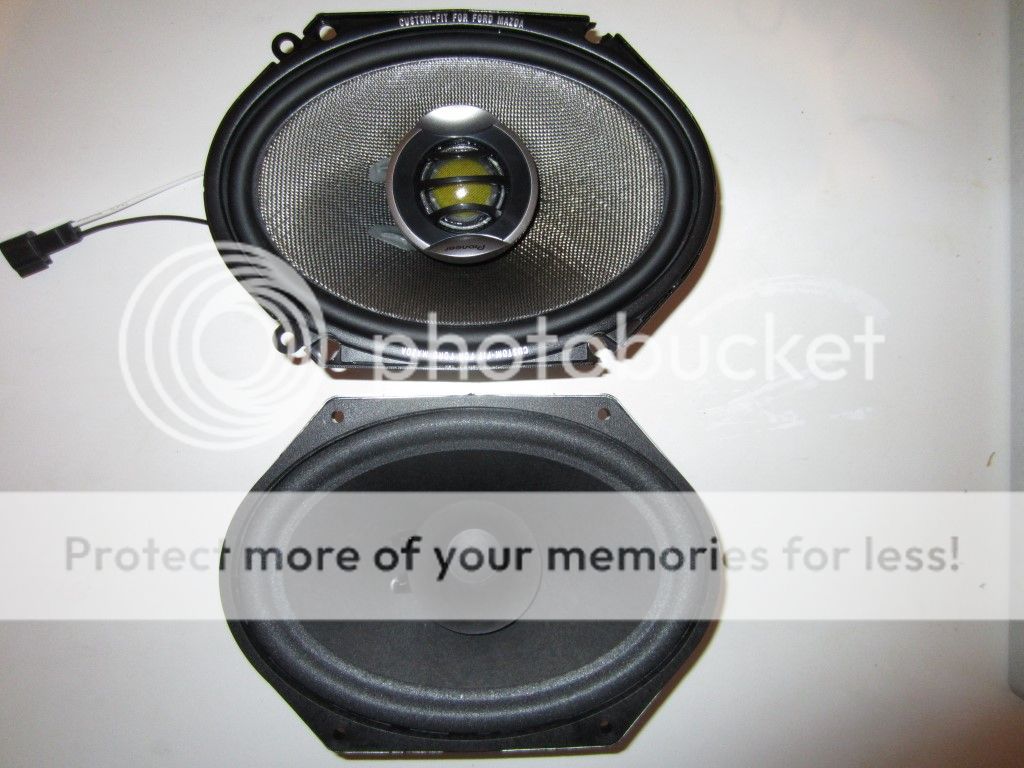
Added a Mitra harness part number 71-048 to the Pioneer speakers, connected them to the OEM wiring harness and secured them with the bolts removed with a 6mm ¼” drive socket and ratchet.

Took the opportunity to clean the interior rear glass and fired up the radio to ensure the speakers worked before starting the reassembly with the X Brace.
For reference here are a few pictures of the components in the Ford Racing Boss 302 X Brace kit, part number M-6346612-B
Bottom cover.

X Brace and Trunk End Trim panel.

Instructions and supplied hardware.

Trunk End Trim panel was the first to go on. Ears secure it at the top with two Torx bolts at the bottom. Using a T 50 Torx socket the bottom bolts were tightened to 20 ft-lbs.

X Brace went on next fastened with four bolts at the top and two bolts at the bottom. Top bolts were tightened to approximately 17 ft-lbs with a 10 mm socket and the bottom two bolts were tightened to 30 ft-lbs using a T 50 Torx socket.

Supplied Nut Clips were installed on both sides of the Trunk End Trim Panel. Passenger side illustrated.

Parcel shelf was vacuumed (might as well take advantage of the opportunity) and reinstalled using four push pins.

Quarter Window Trim Panels were cleaned, reinstalled and the rear defroster wires attached. Leaving the front seat belts off for now as I also have a Corbeau Harness Bar to install. Passenger side illustrated.

Quarter trim panels cleaned and reinstalled. Passenger side illustrated.

Door Sill Scuff Plates reinstalled. Fooled you, driver’s side illustrated this time.
According to the Ford Racing instructions foam blocks were double edge taped to the underside of the Center Luggage Cover. Block were positioned 9” out from the push pin holes and 3.5” to 4” from the front edge.

The two push pins, one per side that retain the carpet were removed. Passenger side illustrated.


The two Trim Bezels where installed over the X Brace upper mounting holes.

Center Luggage Cover slipped into place, not yet secured with the 2 twist retainers on the top sides and the push pins on the bottom front.

So far so good.
AndrewNagle
Senior Member
Very nice write up and execution. Been thinking about this for a while but other necessary car expenses keep getting in the way. Maybe one day
Wild White Pony
Member
I like that a lot!!! Nice work..
Similar threads
- Replies
- 6
- Views
- 590
- Replies
- 10
- Views
- 672
- Replies
- 6
- Views
- 3K
- Replies
- 9
- Views
- 1K
Latest posts
-

-
-
Should I stay away from 2005 to 2008 (spark plugs)?
- Latest: 2019Chieftain-no-more
-

Support us!
Support Us - Become A Supporting Member Today!
Click Here For Details