Vorshlag 2002 BMW E46 325Ci - Daily/Track Car - Project Jack Daniels

Vorshlag-Fair

Official Site Vendor
Official Vendor
Joined
Nov 12, 2010
Posts
1,592
Reaction score
107
Location
Dallas, TX
continued from above

REPLACING A FRONT FENDER

This should be an easy one, but I re-learned a lesson here. The left front fender was smashed when we got this rolling chassis for a song - not a big deal, as I keep a couple of pairs of front E46 steel fenders in stock to use for metal flare jobs on E36 chassis (for before - when there were not good flare options). But it had been a number of years since I had bought these fenders...


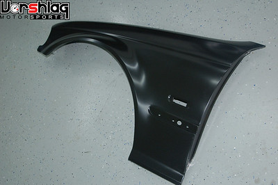
Again, we haven't done a steel E36 flare job like this in years - because there are so many good flares and widebody options for the E36 now. The E46 is no different, as I will show below. But I had forgotten that we utilized E46 non-M SEDAN front fenders for our E36 flare jobs. It came down to the recessed trim section in the sedan fenders was further back and "out of the flare" section. That made the welded steel flare jobs on E36 cars easier. We would cut out the fender flare portion of these E46 fenders then graft them to the E36 (see above right). It was a bunch of work but could turn out nice with a little bodywork and paint.


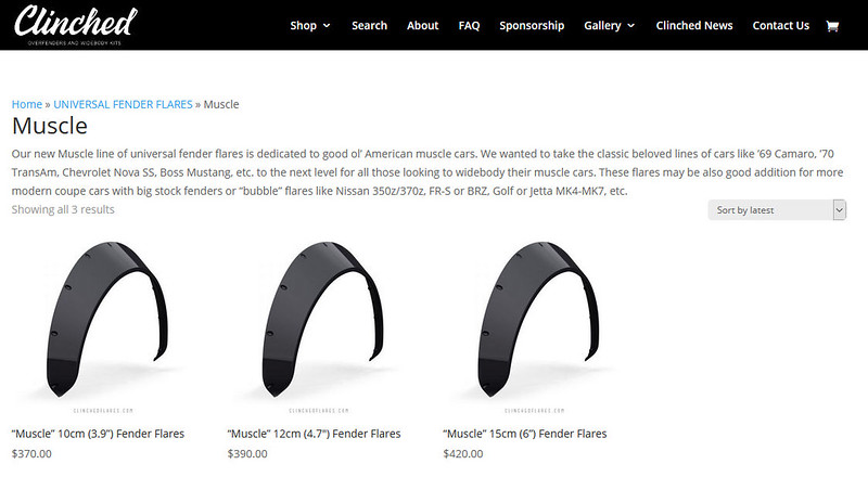
So when the smashed coupe fender was removed, I grabbed one of these SEDAN fenders, not remembering it wasn't a COUPE front fender. It was on the car for a couple of months - because with the front nose and left side door off it wasn't obvious it was the wrong one. If you look at this fender installed, above right, you will notice the body lines from the A-pillar don't match up - that's all that was visible... So when we test fit the Extreme Dimensions flares (shown further below) it "didn't fit".


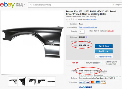
Again - a weird mistake, and it would have been immediately evident if the door was installed. Luckily replacement coupe fenders are still cheap for these cars and I found some for $58 shipped. I used to pay closer to $33 for these import fenders from a local Certifit store, but that's a 3 hour round trip in traffic to save maybe $20. This is one of the few things eBay is good for - cheap used parts or import body parts. Probably won't be the last fender we will need on an endurance car, hehe.

MOUNTING THE NOSE + TUBULAR BUMPER BEAM

We aren't 100% done with this step but I will show some progress. The "M3 style" front bumper cover is an import unit designed for use on a Non-M coupe chassis. This is often used by Spec E46 users, and we will utilize this item for the better grill openings and flatter bottom - which makes adding a splitter easier.


At this point we have the bumper cover mocked up - we needed that for the flare fitment tests. The factory plastic brackets at the tub are holding the receiving "cups" on the bumper cover, with the weight held up by a bucket for now. The cover needs a bumper beam to mount to, with brackets to hold it in place. We plan to have a rolled radiator that is feeding the radiator from the lower grill opening only. to make room for that a tubular bumper beam is a trick we often use to make more room. Here's an example of what we have planned, which we built this year for my wife's LS swapped 86...

TUBULAR BUMPER BEAM ON 86

We almost always start with our tubing roller (below left), install the appropriate dies, and then pick a piece of 1.50 x .095" wall, 1.75" x .095" wall or 1.75 x .120" wall seamless DOM tubing. We cut this to length and then bend the main curve to match the bumper cover.


On this car we were using a carbon fiber aftermarket nose, which had both a curve and needed two bends to kick in for the portions outside of the radiator. Some folks will stop their tubular bash bar at the frame rails, like most OEM beams do. We have seen car-to-car contact rip bumper covers off, destroy headlights, and more. With our full width bumper beams on other cars we have seen our customers "come out on top" of any contact.


Above left you can see how closely this tubular bumper beam matches the shape of the nose we are using - again, necessitating a couple of bends to kick in outside of the frame rails and under the headlights. This FULL WIDTH beam is much stronger and protective than the "half bumpers" we see some build. The mounting plates are cut on our CNC plasma table then the bar is mocked up underneath the bumper cover to figure out the lengths for the tubing mounts. These are fish mouthed and added to the mounting plates and beam. It is all tacked up on the car but finish TIG welded on the fab bench, above right.


These pictures above show the rolled radiator - its also only fed from the lower grill opening, and mounted way forward and down. This makes venting the hood much more effective, and we will do the same thing on our E46. The upper and lower radiator mounts will be custom made, of course. We may or may not make a duct box to the hood opening behind the radiator, but we will definitely make the lower grill opening ducted to the front side of the radiator and oil cooler.


This is as far as we've gotten. On our next weekly work night we should have this tubular beam welded to the mounting plates at the frame stubs, visible behind the bumper in the pic above. Then we will add twin tow hooks to the font, some simple brackets from the tube to the bumper cover, spec the radiator, and build brackets for the radiator and oil cooler. Much more on this task next time.


FRONT SUSPENSION MOCK-UP

We bought this car on very worn OEM struts, springs and "mushroomed" top mounts. After some initial work on one of our 2-post lifts this car was moved to a back corner of the shop for the next phase of work, and the OEM struts were tossed. They were total junk. We needed wheels on the car to test fit the fender flares and for our design work on the Brembo BBK, but the OEM stuff was so long that the ride heights would be totally wack.


Luckily we had an extra Ohlins E46 coilover strut so we found a coilover spring, added a Vorshlag camber plate, and mounted that to the left front. This is not likely our final suspension but close enough for mock-up testing.


One small downside to inverted struts is the spring and body lengths make it harder to fit "the spring above the tire", which limits how far inboard the wheel can fit. Not an issue with most wheel setups on these cars but "We're going to eleven". We need ALL of that room and more. We mounted one of my E46 17x10" Forgestar wheels and 10.2" wide Hoosiers for the next steps.

continued below
 

Vorshlag-Fair

Official Site Vendor
Official Vendor
Joined
Nov 12, 2010
Posts
1,592
Reaction score
107
Location
Dallas, TX
continued from above

MORE DOOR LIGHTENING


In my last post I showed how we got the doors down to 29.0 pounds with some serious cutting, gutting, and removal of the window glass and associated mechanisms. We used a variety of cutting tools to get this structure out - including the plasma cutter and some cut off wheels in a pneumatic die grinder. Both methods are loud, noisy, and messy. Plasma cutter is probably the worst way to do this work, as it leaves a super rough edge that we then had to grind or cut away.


We foolishly forgot to weigh the full weight doors with glass so I don't have a good starting point to reference - but this 29.0 pound weight still seemed heavy for a gutted door, to me. Something didn't "feel" right about that weight. A buddy of mine (Andy) owns Clownshoe Motorsports and said his doors were lighter, so I stopped by their shop one Saturday.


I can't show many of the endurance racing secrets he shared with me that day, but we did measure some various tires, and noted the technique he uses to gut doors. They leave more of the upper structure but remove ALL of the lower structure, and much of the door striker bits. So we took our 29.0 pound doors and went to town on our next work night.


Tim and Jason got to work with the Saws-all and it proved to be a more efficient, less messy tool for cutting the door structures. Leaves a much cleaner edge, too. We cut off the ugly edge left by the plasma cutter and then started to work on the metal below the latch plate.


I then used some extreme care with the cut off wheel and took the upper "crash structure" out at the top of the door, on the inside. The slotted, 3D shape shown in the picture above left. We took this out of the passenger door, and it is heavy. All told we found another 2.1 pounds, which isn't a lot. We had already taken the main crash beam, glass, and regulator out of the door. We were starting to hit a big "diminishing return" type of task.


Tim suggested we KEEP the upper structure on the driver's door (shown with a red box around it, above left). He crews for two different pro level road race teams that have driver changes, and he has noticed that they tend to lean on the upper part of the door during stops. So we left that in the left door, and it is only 1.1 pounds heavier at 28.0 lbs (above left). This door was weighed after cutting some of the inner structure out and with the window + regulator removed, but the diagonal "crash beam" in place at 34.7 pounds (above right).


I made sure we weighed the full weight door (above right) on our 2015 Mustang road race project, which is going on a SERIOUS diet and getting an LS swap. 84.2 pounds for a door is extreme, but keep that in mind when you are gutting your door. We might find another pound in these BMW doors, but we have kept structure at the hinges, striker latch, side mirror mount and along the top of the driver's door. Any additional weight removed is going to make the remaining door compromised... I think we are there.

continued below
 

Vorshlag-Fair

Official Site Vendor
Official Vendor
Joined
Nov 12, 2010
Posts
1,592
Reaction score
107
Location
Dallas, TX
continued from above

BREMBO E46 BIG BRAKE KIT

I teased this last time, and I'm not going to share everything now - because this brake kit is currently untested. We could have just bolted on E46 330 brakes, which are an 1" larger in diameter from the base 325/318/328 brakes, as shown below. We've done this cheap upgrade on a number of 325/328 cars before. But this car is going to be in WRL GTO class (more on that below), with V8 power and 315mm tires... it needs MORE BRAKES.


We started developing this swap kit last June and tested 6 different rotors and a few calipers. I bought a number of rotors, including the E46 M3 325x28mm, the ZCP competition M3 2-piece rotor which is 345x28mm (and $$$), and some other rotors. We mocked up the Powerbrake caliper on a number of these but the prices start ti get extreme if we use that caliper.


We kept coming back to a particular Brembo 4-piston caliper, which we have a lot of experience with. This is not a radial mount Brembo like the Porsche calipers some BBKs are based on. Those Porsche calipers need to be machined and still require a somewhat expensive caliper + core to work.


We attempted to use this with the E46 M3 rotors but the spacing for the Brembo, but with the somewhat "small" diameter 12.8" E46 M3 rotor, the spindle mount spacing just didn't work well for this caliper's mounts. And honestly we wanted a bigger rotor for endurance racing - which is where we see this kit working well, as the E46 is a popular endurance race car chassis. We actually made a bracket to where this Brembo to this M3 rotor but the caliper had to scoot "up" enough that part of the pad sat above the rotor. That's going to make the pads wear poorly so we abandoned this M3 rotor. Shame.


Next we tested a number of larger non-BMW rotors with the same 5x120mm bolt patterns, including this 1-piece 13.6" (345mm) above left and a 1-piece 14.0" (355mm) rotor above right. Even though we would be going to an 18" diameter wheel for our car, we knew many endurance E46 racers wanted to stick with 17" wheels, so we used our 17x10" Forgestar as the "go / no go" gauge for our brake fitment testing. We even tried a 14.5" rotor but it was too tight for safe use inside this 17" wheel.


The best fit for the 4 piston Brembo caliper on the E46 non-M spindle was on the 14.0" diameter rotor (355mm x 32mm), which is a monster. It had the right bolt pattern but we had to slightly re-machine the opening to fit over the BMW hub. Myles used our CNC lathe to make this cut and it worked perfectly. This rotor weighed 24.0 pounds before we machined the hub and chamfer. Very cost effective.


I am not showing our E46 mounting bracket just yet - we made prototype brackets that bolt-on without mods, but they aren't production quality looking yet. Once we get some laps on this brake setup, and if they work as well as they should, we will sell this as a kit (rotor, caliper, bracket and hose). Gives us BIG brakes, affordable calipers and rotors, with a massive pad selection. Fits within some 17" and all 18" wheels. Stay tuned for more.

DURAFLEX E46 M3 WIDEBODY KIT

I teased this last time as the widebody kit had just arrived but we hadn't mocked it up well yet. We needed the bumper cover, left door, a wheel and suspension, and the correct left fender mounted to test flares these completely. All of those other other steps have been completed so now we could finally test fit these bits properly at all 4 corners.


We were excited to try a widebody kit that we could buy for so little. This looked good for both clearance and minimal drag. The aero of a fender or flare matters, especially when you are bombing down the back straight at COTA going 150+ mph. We found out later that the images used by Duraflex on their website are only 3D renderings, and even those are from a competitor.


We got the kit that we ordered (we are a dealer) and the fit and finish was pretty good - we have used a number of items from this brand and quality can be a bit "all over the place", but this was one of the better fitting setups. We spent several weeks rounding up a LF fender, mounting the nose and hood, getting the driver's door on, and mounting the suspension/wheel/tire/brakes - before we could mock these up properly.


These are made to work with the M3 nose and M3 lower skirts, so we had a gap at the bottom where the skirt was supposed to be. But we have some M3 skirts laying around, that won't be a big issue. The fronts and rears both fit surprisingly well. The rear had plenty of tire clearance...


...but the front will only clear a 275mm tire. That's the problem with looking at the drift or stance communities for flare options - they never run a lot of actual tire WIDTH, just going for the stance or a tire that makes lots of smoke.

WIDEBODY KIT FOR SALE!

These flares won't fit over our 18x11" wheels up front, but for a racer or team running a 275mm tire on a 10" wheel, this should be ideal. Interested? We'd sell this whole kit at a loss for $400 shipped - call us at the shop if you want this set. Only mocked up, never drilled or bolted on.

continued below
 

Vorshlag-Fair

Official Site Vendor
Official Vendor
Joined
Nov 12, 2010
Posts
1,592
Reaction score
107
Location
Dallas, TX
continued from above

ORDERING A CAGE KIT

Many of you know that Vorshlag is known for making higher end roll cages in road race cars. But if you have read this post titled "we make roll cages" you might realize that our cages cost a bit of money. Because they take a long time to plan, prep, bend, notch, fit, and weld. 60-75 hours is normal for a car like this.


Spending 75 hours building a cage from scratch - after hours and in our free time - could takes several months to complete. We tried to shortcut this time by ordering a "cage kit" from a reputable shop known for perfect fitting BMW cages. These are pictures of the kit built for our car, remotely, using another E46 coupe chassis to build within.


Back in May the team voted on this option, and then paid for this E46 kit from Hanksville Hot rods. They build their kits inside the same chassis as you ordered - but it took longer than expected to round up an E46 coupe to use. And longer still to complete the kit. Stuff happens.


This was an experiment to see how many hours we could save by ordering a kit and just doing the final welding here. It likely will save a 40+ hours of fab time, once it is complete and in the car, but our 6 month wait to get the kit built did nothing beneficial for our build's timeline. We had hoped to be on track in the Fall of 2019 but we are now pushing into Spring of 2020. We will show more of this kit being installed into our chassis next time, then many things staged behind this will follow.

SEARCH FOR NEW FLARES - CLINCHED

After the Duraflex kit proved to be too small up front for us we immediately started looking for an option that could clear our 18x11" wheel and 315/30/18 tire we will be using. Since 2017 "Clinched" has been making some stancey widebody kits and flares. They make a series of "universal" flares from thermo-plastic, which are formed on a vacuum table - a technique which we have used in the past.

Image1-L.jpg


We had started to see these show up on legit road race and autocross cars with BIG wheels. A buddy had purchased a set of their "Euro" style flares with 100mm (4") widths. They worked to clear a 335mm tire on his Subaru track car (below left) and the same units on this CTS-V road race car looked pretty good. This style is made to be trimmed to fit, then bolted on.


We borrowed this 100mm Euro flare and mocked it up on both ends of our E46 coupe. They have more room than the front Duraflex widebody kit.


This won't be as clean of an install as the E46 specific widebody kit, but it will give us full coverage on the protruding part of each tire, and we can vent behind each tire by trimming the flares short on the back side. We became a Clinched dealer a month ago and ordered a set of flares this week for use on this car. We will show that installation work in a future post.

GTO CLASS + BUILDING THE ENGINE

We have been staying quiet about the engine, but it's Vorshlag - what did you think we'd build? Of course an LS swap is in order for our E46! Look how good an LS V8 fits under the hood of an E46...


An old prototype set of our stainless long tubes was rounded up, we built some mounts, have a brand new transmission which we will test (which I cannot talk about yet), have an E46 M3 rear subframe and diff to use, and more.


Once we agreed upon the class we wanted to run (GTO) then the engine we would use became obvious - an LS V8 engine.


Even running the highest class in WRL (GTO) we are still limited to a fairly tame 9 pound per whp. And unlike NASA ST/TT classes, they calculate with no driver (but full of fuel). We need to know what the car will weigh then figure out how much power we can make...


We haven't done a W2W prepped E46 LS build yet, but we did build a caged E36 with a 427" LS engine and T56 Magnum before. This was our "Alpha" E36 LS build, which we raced from 2006 to 2009. Fully caged, with a fire system, aluminum LS, full exhaust, oil cooler, big radiator, Accusump, heavy 17x11" CCWs, all of the factory glass except the doors (which were gutted), and a single racing seat it tipped the scales at 2508 pounds, without fuel. The E46 chassis is a little bit heavier, plus it will have full aero + driver cooling system - so lets call it 2750 pounds full of fuel and race ready.

2750 lbs / 9.0 = 305 whp

This peak number of just over 300 makes a BMW M54 based engine out of the question. And yes, we could have built a higher strung S54 E46 M3 engine for this car, those aren't exactly inexpensive or known for massive reliability in endurance racing. Costs for an LS are much lower for us, and we are known for LS powered BMWs, which pushed us to an aluminum LS. We could make this with the smallest displacement 4.8L truck engine, or easily with a stock 5.3L. But we are going to "overshoot" our power goals, then dial it back with a using a custom "flat tune" by way of a factory Drive By Wire (DBW) throttle body. You could do the same thing with a physical restrictor in front of the throttle body, too.

continued below
 

Vorshlag-Fair

Official Site Vendor
Official Vendor
Joined
Nov 12, 2010
Posts
1,592
Reaction score
107
Location
Dallas, TX
continued from above

SOURCING THE CYLINDER HEADS

We had just pulled a 5.3L LS based iron block engine from the dead carcass of my old shop truck, a 1999 GMC Sierra 1500, #TruckNorris. This truck was smashed into while I was sitting in traffic by a 1 ton van going 60 mph. Destroyed my truck, bent the frame, shoved me into a parked truck and trailer also stopped in traffic ahead of me. Don't text and drive, kids!


That "LM7" series 5.3L is still an LS based engine, and the "706" castings are a small-valve "cathedral port" aluminum head. This article describes the 706 heads pretty well. They are probably some of the worst performing factory aluminum LS heads out there, but we can still make them work well enough to easily exceed 305 whp - and beyond. This is part of a test...


Erik at Horsepower-Research (HPR, where I am one of the managing partners) is helping us build this car, and will co-drive in endurance races. He disassembled these heads, then we cleaned them up in the aqueous parts washer before running them for about 15 minutes in the Ultrasonic parts cleaner. The flat stone shown above right was used to knock some of the carbon deposits off the block surface, as well as check for flatness. The heads checked out great even after 273K miles of truck use. The ports still had some carbon but the CNC work will take all of that out.

IMG_4077-L.jpg


Most of the valvetrain will not be re-used, and the now bare castings have been sent off to a head porter we use for a "single pass" CNC port program. These will be assembled with steel (not titanium) valves, for our fairly modest power goal. HPR is known for BIG displacement LS engines, but these heads will be a test for an LS engine we want to develop for more economical endurance racing use.

THE INTAKE MANIFOLD

The intake manifold we use for cathedral port heads - along with the camshaft - will determine where in the RPM range the engine will make the most power, and can unleash more on top with aftermarket designs like the Fast or MSD. We might cut the hood later, but we wanted to stick with a low profile "car" style LS intake to start with.


We cannot fit the taller Truck style LS intake (above left) under the hood of an E46, but they do make good power even with a smaller 75mm throttle body limitation. The 75mm mechanical throttle body versions of the LS1 and LS6 intakes are a bit snug to the E46 hood, but we made 490 whp on a 427" LS engine (above right) that was in our Alpha E36, back in 2008 - also built by Erik Koenig.


The other low profile cathedral port intake we can use is from the LS2. These use a 90mm DBW (Drive By Wire) throttle body, which is significantly larger than the LS1 or LS6 intakes' 75mm throttle body. The LS2 DBW throttle body setup is also much "shorter" (front to back) than the later LS6 Corvette DBW TB, and the 90mm LS2 style is very cost effective, too. We have seen a good power bump by going to ever larger throttle bodies... there is almost no limit of how big you can go. 102mm is common and we've seen our 468" LS engine pick up power at 105, 108, and even 112mm throttle bodies.

I did a bit of research on the Dorman brand of replacement LS intake manifolds and this 615-901 "LS2" model with a 90mm TB opening was a real bargain. I hadn't seen much online about this new Nylon intake offering from Dorman so I bought one and we took a closer look. It arrived and looked pretty much just like an LS2 intake. This Dorman intake is only $215.99, and its brand new. A lot of the used LS2 intakes we see for sale have cracked bosses because they are all 10-14 years old. Plastic ages...


The Dorman 615-901 intake's casting looked pretty good except for two locations: There was a weird "protrusion" in one corner of the intake port near the cylinder head (above left), plus the throttle body opening had a lot of weird casting flaws and gaps (above right).


I had engine builder Erik take a look and he said he could fix the flaw in each of the 8 intake ports, then we could port then epoxy the small gaps at the throttle body area. At one of our Team work nights he used a long reach porting carbide cutter and smoothed out the protrusion.


We think this was a flaw in the internal casting dies - something shifted, and nobody bothered to fix it. Same goes for the throttle body section of the casting, where it meets the main plenum portion of the manifold. Just not a smooth transition there, lots of casting flash that had to be removed.


The part is even made in the USA, which is weird. Maybe Dorman will have this worked out at some point - just know this LS2 unit might need some work. He was done porting the intake ports and throttle body opening in about 90 minutes, and I cleaned the intake in the parts washer at HPR later that week.

continued below
 

Vorshlag-Fair

Official Site Vendor
Official Vendor
Joined
Nov 12, 2010
Posts
1,592
Reaction score
107
Location
Dallas, TX
continued from above

THE BLOCK WORK

We wanted to start with an aluminum LS block, as these are 80+ pounds lighter than the cheaper iron LS blocks. We could have sourced an aluminum 5.3L truck engine, which has a 3.780" bore. This is as small as any LS engine (4.8L is the same), and restricts the size of the intake and exhaust valves. So we looked for one of the 3.900" bore LS engines (LS1, LS6), which I happened to have. The 4.000" bore LS2 or 4.065" LS3 blocks would be even better, but those are more costly and I had a clean LS6 block I donated to the cause.


The block was equipped with the OEM 6-bolt main caps (they are worthless without mains!) and it was mounted to an engine stand to take those off.


Once you get the bolts out these mains are a bit tricky to remove cleanly. Erik has this custom set of main cap pullers one of his employees made years ago and I used it to pop the mains out out of the block. Each main was stamp marked before removal, of course. The thrust bearing is on the 3rd main, as shown in the middle of the block in the above left pic. The main bolts were kept but will likely be replaced with ARP studs.


We mounted the block to Erik's mill, which he has setup for block work. The goal was to clearance this block for a 4.00" stroke crank, up from the stock 3.622" stroke crank used in the 5.3L or the 5.7L LS6. If you want to do the math, it's easy:

((3.900" bore ^2) x Pi / 4) x 4.000" stroke x 8 cylinders = 382.3" or 6.3L

This extra displacement only makes the engine more reliable at the power level we are targeting - as we can make more torque at lower RPMs with the added displacement. We do this "make it bigger" trick normally to make more total power, which it does. But on any engine, more RPMs = more problems, and on an endurance engine, we can make the same power goal at lower RPMs. We ran his crank clearance program for this LS6 block and a 4.0" stroke, which takes about 45 to 60 minutes. This is to allow the connecting rod to clear the bottom of the block's cylinder casting with the additional stroke.


Next up the block was mounted to the surfacer, and the decks were surfaced the bare minimum to make sure they were perfectly flat and square to the bore centerline. With less than .005" removed the block cleaned up perfectly. There are more steps - line hone, bearing checks cleaning - but I will show more of the shortblock work next time. And we have a second engine, an aluminum 5.3L, that we are setting up as a back-up engine as well.

2004 330i ZHP

Another customer tired of dealing with lots of little issues like CELs reached out to me this month and wanted to unload this Imola Red 6-speed ZHP sedan. It is out of inspection and registration, and the AC is blowing hot, so it's pretty much unsellable in Texas.


This is a one owner Texas car, however, and it has some tasty upgrades. A 3.64 geared limited slip diff, coilover suspension he bought from us over 10 years ago, 18x9" wheels, Michelin Pilot Sports, a Setrab oil cooler, and more.


With 162K miles, the AC system on the fritz, and these CEL issues it isn't worth a lot of money as it sits - and I don't want to fall into another "let's just find the issue and sell it" trap, as the risks of these being easy fixes are nil. We went and drove the car, however, and it is really nice. Super clean inside and out - this was owned by a BMWCCA member who cared for this car - until it became more of a burden than a joy to drive. I brought a trailer to tow it back home, since it had no plates.


Not really sure what we are going to do with this car - we take it to lunch on nice days and it gives me bad ideas. How about a nice daily driver with a 500 whp V8? I bought this E46 M3 rear subframe (and we have a 210mm LSD M3 diff) just in case we move forward with a swap.

WHAT'S NEXT?

That seems to be enough for this time, but we will have much more to show on the next update. We should have some progress to show on the Team Car ...


We have a few 210mm M3 LSDs and it is cheaper to use one of these than convert the medium case 188mm E46 non-M diff. So I donated an E46 M3 rear subframe (not the same one that I bought for the ZHP) for this E46 endurance car. This has had the bushings pressed out and bead blasted - next time we will show the reinforcements we are adding and the new bushings going in.


We will also show the sealed spherical bushing we installed in the RTAB location, which is pretty slick. Also the cage install, electric assist steering column, and more. Lots to do!

Until next time...
 

Vorshlag-Fair

Official Site Vendor
Official Vendor
Joined
Nov 12, 2010
Posts
1,592
Reaction score
107
Location
Dallas, TX
Project update for March 23rd, 2020: It has been four months since my last post here and a lot has happened - with this project and "the world" in general. As I write this we're in the middle of a global pandemic, but updating this build thread will help clear my mind, and maybe give some of you something to read while stuck at home - hopefully avoiding this virus.


This update is going to be about exactly ONE car this time: our #TeamVorshlag endurance road race car. We're trying to focus on this race car as much as possible, with the resources and time allotted to it. We have installed a roll cage, the LS V8, built the E46 M3 rear subframe, and added some carbon bodywork.


There is a lot of progress considering we work on this one night per week with a volunteer crew. This has gone from a ratty $100 chassis to a proper race car build, with more than a few pro level drivers asking about co-drives. MCS triple adjustable dampers, 18x11" wheels, carbon bodywork, proper aero, and top level safety gear. This E46 is getting pretty serious.


So let's jump right into this build, already in progress!

ROLL CAGE CONSTRUCTION

Last time I showed our cage kit in pictures from the builder (Hanksville Hot Rods), who put it together in an E46 chassis halfway across the country. We received the kit a month after my last post, in December 2019, and we immediately got to work. This included cataloging and weighing the parts, then starting to fit everything into our chassis.


As I write this in March we have everything installed except the door bars, and we've made a few changes and tubing additions. We're saving the door bars for last, as it is a LOT easier to wire the chassis and work in the cabin with those not in the way.


This kit doesn't come with instructions, other than the assembly pictures that Hank sent us as he was building it. But he does mark every coped and fitted joint goes, and every tube is labeled to what it is and where it goes, as are the eight mounting plates. This makes installation pretty obvious.


One of the main aspects that I love about Hank's design - and one that some #CageSnobs and armchair engineers might snipe about later - is where he mounts the main hoop. Instead of sticking it on the floor in front of the rear seat/fuel tank area, he puts it further back and up on a slight shelf, shown above. This places the main hoop about 6" further back than some other kits - and this is crucial.


You have to cut a little flap of sheet metal out of the way, but the lateral structural part of the unibody here is much stronger than the thin gauge sheet metal of the floor. Also, moving it rearward makes it easier to fit drivers of varying heights, and one of our guys is 6'4", Tim Buck, and we have two 6'3" drivers as well. We need all of that room rearward for the seat to slide back, as well as room for the harness bar and shoulder straps.


We started fitting this as soon as the rest of the interior was prepped, and the main hoop was set on the mounting plates shown in the previous steps. We tacked the plates to the cleaned and prepped floor and then the main hoop went in - it was almost touching the B-pillar, which is perfect.


We tried to hold the main hoop then fit the forward A-pillar bars and upper windshield bar but it wasn't lining up. Turns out we need to get the angle of the main hoop set with the rear down bars, so those landing pads were burned in and those rear bars set in place.


The forward A-pillar bars land on this bent landing pad shown above. Once we had the rear fitted it was obvious where this needed to go. Our chassis needed a little persuasion on one side and the paint stripped from both to line them up. I trimmed the corners a bit to fit a bump in the floor on the right side, then Tim cleaned the floors for welding.


Once we had the floor adjusted to fit those front landing pads, the rest of the cage alignment got better. At this point it is mid January and we had a good bit of progress on the cage. Only about 8 hours invested at this point.


The upper windshield bar had two bends and kicked "upwards", and was looking like it might interfere with the windshield glass. The curved "dash bar" also looked a bit challenging for use with an actual dash pad - which we wanted to use. We re-cut the cope the upper windshield bar and trimmed/lowered the A-pillar bars a fraction of an inch, and it fits below the windshield glass.


With the main portions of the caged test fit and tack welded, the harness bar and diagonal were fitted. Then as every section was tweaked and we were happy with the fit, the tack welds were cut. These tubes then were cleaned up at each end and landing pad - the outer surface was sanded clean - then they could be TIG welded inside the car.

MIG VS TIG WELDING

In some cases the whole cage can be MIG welded - and we did MIG the landing plates to the floor pan and chassis. There is usually sealer or paint on the back side that makes TIG welding these plates difficult. Using the MIG we can burn through without issue.


The rest of the joints and junctions were all TIG welded. Why? It comes down to heat - with the adjustable amperage control thru a foot pedal or thumb control, you can control the heat of the weld puddle, which helps control the Heat Affected Zone of the weld. If you get the weld too hot it can cause embrittlement, which is one of the reasons Chromoly tubing is no longer a good choice for road race cages and why we see low carbon 10XX series seamless tubing there (even drag racers have moved to Docal).


On this cage Myles has done most of the TIG work, and he's been careful to keep the HAZ uniform and looking good.
 

Vorshlag-Fair

Official Site Vendor
Official Vendor
Joined
Nov 12, 2010
Posts
1,592
Reaction score
107
Location
Dallas, TX


There are a lot of hours that went into prep work - you have to clean the welded area much better for TIG than MIG welding - to get the welds to look pretty.

FITTING THE DASH + CHANGES

So the dash bar was changed from how Hank likes to make it. His tube is probably stronger, and you can stitch weld it into the cowl structure at the base of the windshield.


The above left pic is how Hank sends the dash bar. It can be stitched to the cowl and is pretty far out of the way of everything else. But it would murder the leading edge of our OEM dash, which I demanded that we use. So we did some work (below) and made this straight dash bar instead. I will explain.


We have a number of spare E46 dash assemblies, including this grey one and the tan one that came in this car. We took the tan dash (above right) and removed the bits we wouldn't use. It weighed in the 12-15 pound range (we will weigh it again later) but after we got a nearly finished weight under 2200 pounds (see bottom of this update) we figured we could afford a dozen pounds for a full dash skin.


The dash mounts to a complicated structure that has a lateral bar that bolts to the A-pillar/hinge areas (see above right) and has a lot of clips and stand-offs that tie into the dash pad itself. Of course we removed the radio, computers, HVAC and other heavy bits - we just want the shell. But the easier way to mount the skin was to tie into the base of the windshield (hence the removal of the Hanksville tube) and then to keep the stock dash bar (the rusty bits above). To be able to fit this OEM dash bar in front of the A-pillar / front down bars of the cage we had to hack away at the ends for clearance, then cut the tube in half.


Of course we could have done this intact if we had planned on using the stock dash bar before the cage was fully welded in place, but once we clearances the ends and cut it in half it could be slipped in place. Then we welded it back together. Obviously the structure of this dash bar is compromised now, with all of these changes. Hence the second straight dash bar that we added and tied into the cage. Again, it seems like a waste of tubing, but it will be MUCH easier to fit the dash skin over this straight bar than the curved bar the comes in this kit.


Me, Tim, and Magan (our newest crew member / future driver) worked all of this out one evening, test fitting and cutting the OEM dash bar until it fit. Then the dash was almost ready to go in (above right). We'll trim the dash pad - carefully and in progressive steps - to clear the A-pillar / front down bars, and then it can mount right to the OEM structure. Extra work but it will provide proper glare protection for the digital dash we will stick inside the stock dash "nacelle", and a dash pad really makes a race car look more professionally put together. With some of the parts we added below you might understand why that's becoming more important.

DOOR BAR CHANGES

So this is where I expect some friction. On the internet "everyone is an expert" and cage analysis is something that borders on an obsession for some keyboard warriors. I've got my own personal design theories here as well, but I understand that there's more than one way to build a safe roll cage.

i-2KMJPB9-L.jpg


This "NASCAR" door bar design that Hank does is a bit controversial, but I totally understand why he makes it this way and agree with the compromises it entails. Look, everything on a race car is a compromise - because everything depends on everything else. Moving the main hoop rearward (a damned good idea) to the point that it lines up with the back of the B-pillar makes for a tough angle to land "outward cured" door bars like this.


This leaves a partially unsupported "S" bend in the door bars, as shown in the mock-up pics he sent us. I'm totally OK with this. And Hank happens to be the NASA Tech Steward for two NASA regions, including Texas. I'm pretty sure he'll sign off on this cage. A NASA log book will get the car into WRL, SCCA, almost any other W2W group recognizes NASA certification.


We ordered the driver's side with this NASCAR style bar setup instead of his optional "X"or even straight bars. Why? Moving the door bar away from the driver and damn near to the skin of the door adds ROOM for the cage to deform in a big side impact. That room allows for energy to be put into the cage instead of your ARM or LEG. Having seen driver's break legs, hips, and arms with crappy door bars I will always try to do this trick.


To avoid the "S" curve you would have to BUTCHER the B-pillar on the E46, and likely most "DIY" cage builders using a kit like his would be over their heads and they'd make a mess of it all. We did the same thing on a 4 door EVO X (above) and had to get special permission from NASA National office to alter the B-pillar. They even made a rule change in the CCR to allow this. But that was a 125 hour cage job, which was a huge money loser. I'm not keen to repeat that time consuming work on our team car.


To save money we ordered the passenger side with the straight door bars. Plenty strong but the difference in room to the passenger is quite a bit. And with half of our team not having any wheel to wheel experience we're going to be utilizing the right seat a good bit for driver coaching before our first endurance race. So we've decided to mimic the driver's side curved bars on the passenger side (above right) - they fit with a change to the coped ends. Will show that work next time - as the door bars will go in last.

TUBULAR FRONT BUMPER BEAM

Last time we showed this curved bumper beam but it wasn't mount to the chassis. We've finished this piece and will show the steps below.


Getting the beam nested inside the bumper cover was part of the trick, pushing it as far forward and as wide as the E46 M3 bumper cover allows. We have zero OEM bumper structure left - this is a crash beam, clear and simple.


Myles spent some time under the hood and working with placement of the tubular beam. Once he was happy with the placement, he and Tim made the stand-offs that were then tack welded to the flanges we cut on the CNC table (we've started making these bumper mount flanges, after a racer saw the last build update and wanted a set).


continued below
 

Vorshlag-Fair

Official Site Vendor
Official Vendor
Joined
Nov 12, 2010
Posts
1,592
Reaction score
107
Location
Dallas, TX
With the beam tacked to both ends of the stand-offs it was pulled and fully TIG welded on the fab bench. I missed getting an "action shot" of this work but Myles got this welded up, even added some triangular gussets (shown below).


I asked Myles to look at the tubular beams we've made for two other E46 models and the bracket above is a reflection of that. He made one flat mock-up that didn't work out (above right) but when he added the bends with the box and pan brake (above left) the 18 ga steel bracket really stiffened up. Adding some dimple die holes also reduced weight while firming it up even more.


This bracket was then welded to the bumper beam and the top edge is what the top of the bumper cover sits on. We'll add a few nutserts to the bracket and some counter sunk bolts till attach the bumper cover to the bracket.


The fully welded bumper beam was bolted to the frame stubs and is rigid enough to jack up on, add jack stands to, etc. This allows the bumper cover to finally be supported along the front edge. We'll still add two two hooks to the beam, splitter stand offs, and some brackets on the edges for the bumper cover. Will show that next time.
 

Vorshlag-Fair

Official Site Vendor
Official Vendor
Joined
Nov 12, 2010
Posts
1,592
Reaction score
107
Location
Dallas, TX
continued from above

DRIVETRAIN INSTALLED

We had a bit of a dead line for a "show and tell" meeting with a supplier in February 2020, who needed to see this race car. It was a good incentive for us to push harder and get more things done to the E46 - like installing an LS engine, installing suspension, having the cage mostly done, nose mounted, etc.


We had the "backup" aluminum 5.3L long block up at HPR but brought it back and mounted a real road race style oil pan to the engine, then stuck it into the car.


Of course we had a bunch of LS swap parts we sell to use for this, but luckily we had some early prototype headers, our original prototype mounts, and a few other leftovers to use. This Summit steel road race oil pan above fits with miles to spare - something we wanted to test on this E46 swap anyway.


We built our shop 2015 Mustang #LS550 swap around this oil pan, and it seems to fit anywhere the 1998-02 Camaro pan or any of the Holley LS pan fit. We will test this in this road race setup on both the 5.3L and the 6.3L stroker that will go in later. With a wet sump oiling system and an Accusump, of course.


Great fit on the kick-out style oil pan, so we'll keep that. The oil filter mount comes off for use with a remote filter and oil cooler, which we will show later. Found these tall LS valve covers with the "CHEVROLET" script, and we will use these with remote coil mounting.


This is a Gen IV truck engine - which all come with DOD features we have to bypass. This requires a unique upper cover (ICT Billet, shown above), and Gen III style front cover, timing chain, cam shaft, and lifters. We're going to do initial testing with this 5.3L so we're getting it ready.


Then we installed the Dorman "LS2" intake and a 90mm DBW throttle body. Then a set of our E46 stainless long tube headers.


That's as far as we got for the show and tell - the motor has since been removed and then reinstalled with a new transmission.

E46 M3 SUBFRAME WORK

As I mentioned last time, we had a few 210mm M3 diff housings (which come with limited slip differentials from the factory) and two complete E46 M3 rear subframe assemblies, as shown below left. Everything on the E46 M3 version is stronger - the differential housing, trailing arms, rear brakes, and more. The E46 non-M rear subframe (see below right) has a number of disadvantages.


In the long run it will be more cost effective for us to convert our 330Ci chassis to use the E46 M3 rear subframe and M3 diff than to convert the 188 mm Medium Case E46 housings to limited slip.


Since none of the "non-M" E46 cars ever came with a limited slip, and many of those medium case housings have a ring gear welded to the diff case, it can get pretty costly to convert one to limited slip. I've done this conversion on non-M E46 cars a few times and it is always shocking how costly this is to do. The differential mounts on the non-M case are also different, and less than ideal (see above right). The available gear ratios on the larger M3 housing also work better for our V8 engine. We will be beefing up even the M3 bits, and will show the various steps below.

STITCH WELDING, REINFORCEMENT, AND POWDER COATING SUBFRAME

We have a few complete E46 M3 rear subframe assemblies, brake to brake. We buy these when they come up for sale, and in one case we had a rusty version that was in a northern car that we picked up cheap. We took the ugliest of our available rear subframe assemblies apart to use for this project.


This involved removing all of the subframe bushings, shown above left. This took a little work but they came out relatively uneventfully using our many BMW specific bushing tools.

continued below
 

Vorshlag-Fair

Official Site Vendor
Official Vendor
Joined
Nov 12, 2010
Posts
1,592
Reaction score
107
Location
Dallas, TX


You can see the rusty surface of this subframe housing, above. It wasn't deep rusty, just ugly surface stuff. I took this and dropped it off to be bead blasted in November 2019. We got it back in mid December but didn't get a chance to work on it further until January 2020.

SEALED SPHERICAL RTAB BUSHINGS

While the subframe was coming apart we decided to test a new product we had found. The Rear Trailing Arm Bushing (RTAB) on the BMW E36 and E46 chassis is a complicated joint that has to pivot and rotate in 2 different axis.


We don't use polyurethane in this joint, ever. Instead, for the past 16 years we've been in business, we press in an OEM rubber bushing + our RTAB "limiters", which we machine from UMHW for its self-lubricating properties - as shown above. This limits how much toe change can happen with full articulation of this rear trailing arm. A better solution for a race car is to use an aftermarket spherical metal bushing assembly here. The former works well on street and dual purpose cars, the latter not so much. A little road grit + rain will quickly wipe out an all metal bushing located so close to the ground.


For this build we wanted to try a new "sealed" spherical bushing that Jason found. This should give us the best of both worlds. Water proofing a spherical bushing (like BMW does for some other rear suspension locations) would allow for full articulation in 2 axis, without the rattle and bang that worn sphericals give you in a short amount of street driving. Tim removed the M3 rear trailing arms (above left) from the subframe, then Myles and Jason pressed out the old bushings.


We found an OEM replacement sealed spherical that was almost the right size and we made it work in this location. It wasn't easy, and it took some custom machine work and some other compromises. For now we're not releasing what we did or offering this as a kit to sell until we can test this car on track. With a little bit of work we think we can make this easier to install for the DIY crowd.


We installed and fitted the bushings on the two sides two different ways, testing two methods. It was "more than a press fit" getting the spherical housing into the Rear Trailing Arm. Once we got the fit where we liked it, they were both pressed into the arms with the giant C-clamp bushing press shown.


For now this isn't an easy "DIY" job but we're working on some other ways to make this work better. The articulation is perfect (above right) and should be the right solution for E36 and E46 chassis cars, once we can make the bushing more perfected for this application. More on this later.

REAR SUBFRAME REINFOCEMENT

There were a number of things I wanted us to stitch weld as well as some reinforcements to make.


Up first was a pair of brackets that held the rear swaybar. Nobody makes a reinforcement kit for the E46 M3 subframe so Myles drew up and CNC cut out these plates above.


Likewise the two rear differential cover mounting brackets looked a little underwhelming, so I asked Myles to make the brackets above.


After he made some cardboard templates and we discussed a number of tweaks it was time to turn them into CAD drawings then CNC cut them on the plasma table. After they are cleaned up and bent they fit these locations well. After showing the picture above a number of folks reached out and we have made this E46 M3 kit available.


Myles TIG welded these reinforcements to the 4 locations we wanted to strengthen, then stitch welded a few spots that the factory skip weld. This is part of why we bead blasted the whole subframe - it makes for cleaner welds, shows any flaws hidden under the factory paint, etc.
 

Vorshlag-Fair

Official Site Vendor
Official Vendor
Joined
Nov 12, 2010
Posts
1,592
Reaction score
107
Location
Dallas, TX
REAR SUBFRAME AND DIFF BUSHING INSTALL

After we got the rear subframe back from powder coating it looks beautiful. We rounded up a set of Powerflex "race polyurethane bushings for the subframe (4) and differential mounts (3). Some might find our choice of poly unusual, as there are Delrin and even aluminum options for all of these locations. Well having done all of that before we knew that this option would give us the least NOISE while controlling any unwanted movement. Aluminum bushings in particular make for a lot of loud crashing and banging, which can be unsettling in an 8-24 hour race, over and over.


Brad pressed in the bushings into the housing (above left), which had already been removed before blasting. The diff housing was then tackled with some special tools we have just for these 3 locations.


Two of the bushings for the M3 housing are in "ears" that extend out from the aluminum rear cover. These are relatively easy to get to. The front bushing is near the pinion flange and goes in the right side - it is pressed into the subframe assembly, and is a little trickier to get to. The diff housing then bolts through this bushing to mount the front.


With all of the bushings pressed into the subframe and diff housing it was time to joint them together, shown above and below.


This selection of "harder" durometer polyurethane bushings should provide the control needed between these two pieces, which normally rock and roll around on very soft OEM rubber bushings. This movement, of both the diff to the subframe and the subframe to the chassis, is what causes so much flexing of the sheet metal tub - which leads to cracks that have to be repaired. We will fix this by adding reinforcements to our chassis in a later update, of course.

3D SCAN + E46 SEAT BRACKET DEVELOPED

One of my goals for this project it to develop new products - and one area we have been pushing into lately is seat brackets. I moved us into this arena reluctantly, but since many of the chassis-specific seat base bracket offerings out there are so terrible (too tall, too flexible, not safely built) that I felt we were doing the community a disservice by staying out of this area.


I wrote this forum thread last year explaining the "what, why and how" of our unique form of seat brackets. We have made these for 5 different chassis now and will be offering the E46 versions soon after I post this. We make these to bolt to the chassis, have mounting holes for lap and anti-sub belt anchors, and leave a swatch of metal that the end user drills and bolts their side brackets (fixed) or sliders to. All of these designs are minimally tall and have reinforcing ribs underneath, and we make them 100% in-house with CNC cut parts, TIG welding them on production fixtures.


We normally take manual measurements of each chassis' four factory mounting holes, but this time we were willing to try some new technology - 3D scanning. A helpful sales tech came by to demo his scanning products and used this chassis for the test. What it gave us was a point cloud that we could then translate into a CAD design. Don't know if it really saved much time, but it was cool watching this tool being used.


Myles turned that into a working prototype, which he CNC cut and we tested in the car (above left). The E46 chassis is pretty narrow and what he realized pretty quickly when this prototype was placed in the car is - we usually offset a racing seat pretty far towards the tunnel. The factory steering wheel isn't even centered on the factory BMW seat. So I worked with him on version 2, which has this offset built in, that he cut, tested, then welded in the reinforcing ribs for (above right).


Tim worked on the sliders and side brackets, which were tested on the seat, then the holes were transferred to the bracket (above right) and the sliders + brackets were bolted into the car. So we have one seat mounted. As soon as we make the passenger side version (they are sometimes mirror images of the driver's side, sometimes now) we will release this as a bracket to sell.

NEW DAMPER SET - MCS TRIPLES

For the past several months our E46 had been up on jack stands and stuck in this cramped work bay. This was because we had removed all of the OEM suspension and had only mocked up up one front corner with a strut/spring/top mount. This let us work on the big brake kit there but we needed to get this car down on the ground and mount up some wheels and tires to move forward in the build. This meant we needed a set of coilover shocks.


We had put out the ask for a little while, and MCS came through in a big way. Getting triple adjustable MCS dampers for this car was the culmination of a lot of hard work, a long record of MCS sales and race wins using their parts, and a little begging.


Normally we will stretch our budget to go for internal doubles (TT2) or remote double (RR2) adjustables on our shop owned cars - which tend to be focused on Time Trial and autocross competitions. My S550 Mustang has RR2s, as does my wife's Optima entry, an LS powered 86. But MCS felt that the triple adjustables were worth it on this endurance road race car.


The triple adjustables give us low speed Rebound, low speed Compression and high speed Compression adjustments. This is especially helpful on a Wheel to Wheel race car where "defending your line" means using a bit more curbing than you would in a TT or HPDE car. The rear shocks are setup to run as a coilover, which we normally don't do for various reasons on the E46 or especially E36 chassis BMWs.
 

Vorshlag-Fair

Official Site Vendor
Official Vendor
Joined
Nov 12, 2010
Posts
1,592
Reaction score
107
Location
Dallas, TX


We got to work quickly installing these onto our E46. The front was a simple bolt-on affair with springs we had on hand. We needed that end on to be able to spec the front wheels - which we try to keep as far inboard and as close to the strut as possible.
 

Vorshlag-Fair

Official Site Vendor
Official Vendor
Joined
Nov 12, 2010
Posts
1,592
Reaction score
107
Location
Dallas, TX
continued from above

Out back was a bit trickier. MCS wanted us to run their inverted, eye-to-eye style rear shock with a 22mm shaft and coilover spring mounting, using a dual / helper spring setup to keep the tire loaded - even at full droop.


This required the use of the MCS "eye" upper shock mount, which bolts into the stock shock tower (see below). Brad mounted that and I was happy with how much inboard wheel clearance we still had. Whew!


This type of spring mounting can sometimes compromise inboard wheel room - a coilover rear on the E36 chassis absolutely will eat up tire room, but the E46 chassis does not suffer from this space constraint. We will need to reinforce the rear shock tower to take full suspension loads, instead of just damper loads, however. We have some ideas and will share that work in a future update.


Brad handled this MCS install in early February 2020, which let us mount the 17x10" wheels and roll the car out of that back bay for the first time in months. Big step, seeing the car down on 4 wheels and rolling again!

FLARES ON & 18X11 WHEELS ORDERED

Shortly after getting the suspension installed we were able to get the E46 over to a 2-post lift and up in the air.


I asked Brad to temporarily tape the Clinched flares (we showed last time) to the car at both ends on the driver's side. These are made to be "trimmed to fit" the contours of your car, and this is where the look and fit of these will improve. For now we're just taping them in place.


This let Jason come out and inspect the clearance inboard, outboard, and relative to the flares. These flares are going to be big enough for our 18x11" wheel and 315/30/18 (or thereabouts) 200 treadware tire package.


The test wheels shown here are NOT our final race wheels, and they are already 10" wide. We're looking to add another inch of wheel width and a good bit more tire. The "stock vs flared" pictures above should show how much room we gain with these flares. Jason was able to spec the wheels so that the same set can be used front and rear (fewer spares needed, and they can rotate) with a 12mm spacer up front, which is normal for most BMW wheels. These wheels were ordered from Forgestar before their additional bespoke wheel charge came into effect, which was a bit of a surprise in March 2020 when that came down.

RADIATOR SUPPORT + HEADLIGHTS MOUNTED

We had been debating head lights to use and how to mount them. The factory "radiator core support" (shown below) is the easiest way to mount the headlights, but it has a bunch of structure we don't need. We have bought a number of these over the years from the import suppliers and they all worked just fine. Looking through our pile of spares we had another brand new one in stock, so we decided to splurge the $55 already spent and use it.


Our car didn't come with one, as it had been in a front end hit. These are pretty common to replace after any small accident, and BMW keeps them painted black no matter what color E46 they made. It didn't take Evan more than a few minutes to bolt this in place, then we started looking at the extra plastic clips and mounts needed to bolt the headlights in place.


Instead of ordering a half dozen special clips from Germany we decided to add nutserts into those square holes in the core instead. Evan drilled the square holes round, then installed some M5 rivnuts. We used some old headlights to make sure they lined up and they did.


The radiator support was then cut up quite a bit - looking for room to fit the radiator. Our goal was to open up a narrow spot and then shove a wider than stock radiator and roll it forward into all of this area we added by making a tubular bumper beam. Unfortunately the headlights themselves are wide and we don't gain a lot of room between the lights to roll the radiator into. But we did remove a lot of structure that was blocking airflow.

The "mock-up" headlights we had on hand were fitted in place when the rivnuts were being added. These looked rough, and were some old OEM units we had leftover from a customer's build when we installed new headlights and turn signal housings on his M3. Tim wondered - can we clean these up and use them? I was doubtful...


Now for headlights I was ready to spend a few hundred on some nice aftermarket replacements but these aren't really needed on this race car. The halos, the smoked turn signals, not really worth it. These are some I purchased for another E46 we covered in this same thread, years ago.
 

Vorshlag-Fair

Official Site Vendor
Official Vendor
Joined
Nov 12, 2010
Posts
1,592
Reaction score
107
Location
Dallas, TX


Brad brought out his headlight polishing kit and got started wet sanding and polishing the lenses...


They cleaned up pretty well, surprisingly. Enough to not be an eye sore for our "show and tell". I still might buy some new lenses later (they are amazingly inexpensive) and we can install those with some very bright LED bulbs from Diode Dynamics. Possibly even some yellow XPEL film to protect the new lenses. Will show more here another time.

SHOW & TELL / WEIGHT CHECK FEB 2020

Many months of work and a bit of a thrash in January and February came to a head when we got the car on the ground, on MCS dampers, with an LS engine and headers installed, wheels and tires on and rolling, headlights, M3 bumper cover, bumper beam, and the red steel hood installed.


Since we had the car on the lift we installed one of the Sparco race seats, a radiator, stuck both doors in the back, the heater box (which I haven't showed yet) was set inside, and the electric steering column (also not shown much) was bolted in place. This car has both front 14" rotors and one of the Brembo calipers, and the E46 M3 rear rotors are installed. All of the tubes from the cage kit were inside the car, if not welded in place already. Still has the old non-M subframe and diff, for now. We even loaded the clutch, flywheel and pressure place inside. A Mishimoto radiator was set on top of the engine, and a 22 circuit wiring harness was placed into the trunk, too. Then we got this weight.


2112 pounds was lower than any of us guessed, but a decent amount. We're still missing the the transmission + bellhousing, windshield, driveshaft, swaybars, plumbing, fuel tank + fluids, and the larger E46 M3 diff housing is going to be heavier than the medium case in the car now. But the steel hood and trunk are being replaced with carbon, which will save a little. So we're off by 200-300 pounds. Still, it was a very encouraging number.


Due to this latest weight check we have a good idea of where we will end up now, and this is helping us make smarter decisions as we wrap up the build. We will of course keep taking weights and posting them, even if the car is incomplete. These data points have been helpful to some.

THE CARBONING!

On March 3rd I was working late and a freight truck arrived at 7 pm, in the dark, while raining. I had to scramble a bit to get the fork lift hooked up and unload this big pallet of carbon fiber parts. I dubbed it "The Carboning!" and was as excited as a kid on Christmas.


We unloaded the pallet the next day and unboxed all of he Anderson Composites and Seibon parts. These are two sides of the same company, with Anderson being their domestic car arm and Seibon the import car arm. For our S550 Mustang I received a carbon trunk and carbon doors, shown above.


For our BMW E46 project we got a carbon hood and a carbon trunk. The quality and finish on all of these was great. These Seibon pieces are not "dry carbon" motorsports parts (which they also make) but their more affordable carbon-over-fiberglass / shiny gel coat versions. Still lighter than stock, but not as light as you could see.


Of course we took weights on everything. On the trunk we went from a 27.7 pound steel unit to a 15.6 pound carbon unit. That's a 12.1 pound drop, or a savings of 43%.


The steel 330 hood was 44.5 pounds, and the carbon version was 24.2 - for a drop of 20,3 pounds and a savings of 46%.


In addition the new hood is the "bulged" M3 style and includes a set of carbon grills (which are removable) as well as four massive, carbon vent panels (also removable). The outside carbon surfaces are very glossy and the weave is laid out nicely.
 

Vorshlag-Fair

Official Site Vendor
Official Vendor
Joined
Nov 12, 2010
Posts
1,592
Reaction score
107
Location
Dallas, TX


Brad installed the Seibon trunk in about a half hour, just needing to shim the hinges a bit to get the body lines perfect. This required zero sanding or trimming of the actual part, which is pretty rare for composite parts.


Jason and I spent about an hour and a half fitting the hood. This was mostly due to the poorly aligned front fenders, which had huge gaps to the steel hood. We slotted some of the mounting holes there and got the body lines pretty darned good, too. Really looks good with this carbon installed, of course.

LED TAIL LIGHTS, SUNROOF PANEL, PEDALS

This car was missing anything and everything of value, and that included the pedals. After getting a loaner set that I had to give back I broke down and ordered a clutch/brake pedal assembly for $102 shipped from eBay. Tim got those installed on a work night pretty quickly. Installing those allowed us to bolt on the E46 brake booster we had, on the other side of the firewall.


We found an SSR fiberglass sunroof panel that I had ordered back in 2015 for another E46 coupe, and this will be used on this car now.


Another missing part on this chassis were the rear tail light housings, along with the trunk mounted reflectors. I bought a set of the brighter LED versions for this E46 coupe.


Tim installed these into the carbon trunk in early March - nothing tricky here, just a straight bolt-in. As we have done before, we will "direct wire" these around the CAN network that normally controls these brake/tail/turn/reverse lights. We're replacing the entire wiring harness on this chassis.


This set of LED tails + carbon trunk really set off the back of the car. We have a new, fake, custom license plate we will add and show next time, too.

WHAT'S NEXT?

That's a big chunk of work to cover this time. We have other work that has been completed but we're not ready to show all of that just yet - like a brand new crossmember to support a new transmission for this E46 LS swap. Lots of parts have arrived for the front suspension, too.

IMG_7143-S.jpg


New inner/outer tie rods, Lower Control Arms, and these LCA bushings from Whiteline with a 2-piece bushing (that allows for proper articulation). We're using this car as a test bed, remember - and this is a new part to us. Rear subframe reinforcement work needs to be done, exhaust needs to be built, and more.

blog-post-header-e46-gmt800-L.jpg


At the same time as this E46 endurance car update was written we also posted an update on our GMT800 shop truck build thread, which went through a ton of changes. You can read that here.

Until next time... thanks for reading!
 

Vorshlag-Fair

Official Site Vendor
Official Vendor
Joined
Nov 12, 2010
Posts
1,592
Reaction score
107
Location
Dallas, TX
Project update for September 23rd, 2020: It has been 6 months since my last post here, and not a lot of things went according to plan. We got crazy busy during the pandemic, lost some manpower, but we are still working on our E46 endurance car a little every week. I spent part of Labor day weekend writing this update to catch us up to the present, which helped me realize I needed to order a few missing parts, as well as update some product entries for things we sell for E46 models. Then I got busy and had to re-start my write-up again.


There is some progress to share, with some "backwards" progress in one area, and nothing happened as fast as we liked. As racing resumed, so did the pro racing support schedule for two of our team members, Tim and Magan, who regularly travel to events for trackside support. "Luckily" none of the other Vorshlag shop cars are complete so I wasn't out for almost any of 2020 going to races (this actually sucked). More time to work on this car - and more motivation.

MOCK-UP ENGINE REMOVED

After our show-and-tell with the E46 we pulled the mockup engine out for the last time. We had the new transmission crossmember developed, test fit two new oil pans, and learned a lot with this task.


Pulling the radiator support out makes for a FAST drivetrain removal (engine and trans together), and I encourage any endurance racing team to make that happen on their cars. Removing engines is often a necessary task.

DASH GUTTED AND MODIFIED DASH BAR INSTALLED


So the dash bar (above) that came with the Hanksville cage kit was made to go pretty high up and would pretty much preclude the use of the dash. And I really wanted to keep the OEM dash pad, for appearances as well as to make for better "glare protection" and gauge visibility on sunny race days. So it was time to make some changes to the cage. We looked at the OEM dash bar, which has all sorts of integrated bracketry to hold the dash pad.


In March on one of our work nights Tim, Magan and I tackled the dash mockup while Myles was welding on other parts of the cage. We removed the Hanksville dash bar and mocked up an OEM dash in the car (we have two - tan and gray ones). There was going to be interference and notching needed but there wasn't an elegant way to mount the shell.


We removed the dash bar structure from the dash shell and started hacking away at it. To fit it between the two main A-pillar down bars we had to cut the OEM dash bar in half.


We cut the main bar to the right of the steering column support, notched the ends to clear the down bars, and put it into the car. Then tack welded it back together.


This way the dash pad has some of the OEM structure - which is a lot better than how some dash pads get installed. I cannot stand a floppy dash that is bouncing around willy nilly.


Since we compromised the structure of the bolt-in dash bar (we really had to hack up the ends) as well as cut it in half. We built a new straight dash bar to mount just next to the OEM bar. This is going to be hidden under the dash but this one has real structure and ties into the cage in case of a side impact. We will tie the OEM bar to this one, for the structure needed to hold the column. We still need to notch the plastic dash pad to fit around all of this, but I will show that in a future update.

COMPOSITE REPAIR + PROP ROD VS HOOD STRUTS

The composite Seibon hood (24 pounds) is considerably lighter than the stock steel hood (42 pounds), but it is weaker in some ways also. When some of the crew were man handling the hood into place back in March they only had one bolt on one side fastened and somehow with the hood struts installed on that hinge it was tilted, which cracked the mounting flange for the hinges on one side. I've seen similar damage done when using (mostly aftermarket) gas lift hood strut kits.


I was less than thrilled, but "stuff happens" and at least it wasn't a customer's car. Evan extracted the threaded insert plate that had pulled out and sanded the areas to be repaired with more layers of glass and resin.


He cut a space for that into the composite then used fiberglass mat and resin to cover that plate and reinforced the whole area. A little primer and it is as good if not better than new.


We installed the repaired composite hood for a while with one new OEM gas lift strut on one side, but it still felt like the hood was going to fly off when we lifted it up. Just sitting there with the hood up it was bending that side, so we had to do something different. I had an idea...


In late August I installed this S550 Mustang hood prop rod setup. This is an aftermarket, stainless steel version of an OEM prop rod made for 2015-up Mustangs, which was easy enough to install. I added an M6 threaded insert to the radiator support and bolted it on during one of our work nights. Still might tweak this a bit after we get the cold air intake hose and airbox in, but this way we can hold the hood up and NOT have the gas struts trying to bend the hood in half.
 

Vorshlag-Fair

Official Site Vendor
Official Vendor
Joined
Nov 12, 2010
Posts
1,592
Reaction score
107
Location
Dallas, TX
PEDAL BOX INSTALL

This car was stripped of the pedal box. We had a loaner for a bit to do some initial mock-up, but we needed to buy our own set of E46 manual transmission pedals and I found this on eBay - the home for junkyard parts.


These bolted in back in late February, but we have not yet installed the throttle pedal. We're using a modified LS3 Corvette Drive By Wire pedal compatible with the Holley Terminator X-Max EFI system we chose.


We have made a lot of these LS3 brackets for various one-off LS swaps in the past, but for the E46 we are going to create a production pedal bracket kit - like we did for our S550 Mustang LS swap (above). We might incorporate the mounting into the Prius steering column center bearing adapter mount, too. More on that soon.

MORE CAGE INSTALLATION

Normally when we take a cage job we can knock it out in a few weeks. Or sometimes it is built in stages over the course of a major build - like when we have to do a lot of wiring or interior work, we want the door bars to go in last, as they are a struggle to work around once in place.


In this case, we're doing the cage work at best for a few hours one night a week, with one fabricator who has a lot going on (Myles). He is also an engineer, CNC operator, and just had his first baby - so he's been pretty busy! Since our last post he has tackled more of the TIG welding and Tim has helped him on a few custom bars (changing the "X" bar we ordered to a NASCAR bar on the passenger side). We did add invest in an air-over-hydraulic kit for our JD2 tubing bender, which makes new tubes easier to make and bends are more accurate.


So the cage is making progress, just slower than we would on a customer's car - because we don't have 8 hours a day or a full time fabricator to tackle the cage work on this "after-hours" employee build.


The main tubes are all in place now and we are just waiting to finish weld in things like the dash bar, an FIA vertical bar we are adding, and one roof bar.

ELECTRIC STEERING COLUMN + SEAT MOUNTING

We have been talking about using an "Electric Power Assist Steering" (EPAS) column in this car since the beginning but I have not shown that yet. Why? because unlike aftermarket supplied units we have used in the past, we're trying to do this with cheaper OEM based column.


The aftermarket EPAS unit above worked well enough in this V8 E46 M3, and I got some good first-hand experience with this on track this January. But it was expensive ($1800-ish) and required a lot of work to join their electric motor to the E46 steering column. It does have a steering force controller on a dial, which is nice, but it wasn't working 100% of the time in our track test. We're chasing issues with that now.


Instead we're trying to make a steering column from a Toyota Prius model retrofit completely into our E46 330 endurance chassis. This could make for a lot less hassle during the install or for replacements later (expect everything to break on an endurance car at some point). We have researched several units and some racers have used the 2004-09 Prius unit (above right). But we have very different height drivers in our car, so the tilt/telescope feature of the 2010-14 Prius might work better for us. We bought both to test with.


Myles has designed and cut out a couple of different brackets that were bolted or tack welded to the BMW steering column mount, to test both the early and late Prius columns. The column was "clocked" so that the motor was not down by our legs this time, as shown above.


To complicate matters the chassis we started with came with no steering column at all - it was pretty stripped - so we didn't have a good gauge of where the steering wheel should be. So we paused the steering column testing for a bit to wrap up the E46 seat bracket base, get the seat installed on a slider as low as possible, then proceed with more Prius steering column mock-ups.


It wasn't until the seat was mounted and the cage largely complete (late April 2020) before we could "test sit" the column. Above is the early tilt version shown at two tilt heights. We could never find the correct Toyota wiring diagrams and pin-outs for the later tilt + telescoping version, so that version will have to wait. We got some schematics, but they were wrong and didn't match the 2011 column we bought.


Tim sourced a Flaming River U-joint that ties into the base of the steering column's intermediate shaft splines and goes to a 1" DD shaft. We then connected the other end to another shaft that will have our BMW 54 spline U-joint at the steering rack. A "center bearing" at the fire wall is needed to keep this multi-piece shaft lined up (a support bearing at the firewall is normal).
 

Vorshlag-Fair

Official Site Vendor
Official Vendor
Joined
Nov 12, 2010
Posts
1,592
Reaction score
107
Location
Dallas, TX


We have the center bearing and will fab up a plate to cover the MASSIVE hole in the firewall from removing the OEM bits there. We have since wired in the early Prius column and await getting the car back on the ground to test this further. I made some progress on the custom, bolt-in "filler" panel that will mount the center bearing, which I will show next time.

CHASSIS AND EFI WIRING

Not much to show here yet - just that we ordered and received our Painless chassis harness kit with fuse box as well as the Holley Terminator X-Max harness and computer to run the LS engine.


We will use the Painless harness to replace the missing OEM chassis wiring harness and fuse box, and the Holley system will tie into that to control the engine. Will share more when we have progress to show.

DE-POWERED STEERING RACK

On a work night in late May 2020 Tim started tearing down our E46 steering rack to "de-power" the hydraulic power assisted unit. This will remove some resistance internally and allow the EPAS column to add the power assist, removing high pressure (and flammable) hydraulic power steering fluid from the car.


After we power washed the exterior of the rack, Tim tore it down like he would any Miata rack - which he has de-powered many times. The pinion was removed, then the rack portion. On the horizontal shaft in the rack, the separating piston was removed.


This is what allows for the assist - as hydraulic fluid pushes on the piston left or right. With that piston removed - viola! - it is de-powered. He re-assembled the entire unit with grease (the pics above, shown out of order) and then got it ready to go back into the car with new tie rods and boots.


HPR 6.3L "STOLEN" + REFRESHED 5.3L LS V8

I showed the Horsepower Research 6.3L cathedral port LS engine build slated for our endurance car here in a previous installation. That was completed during the 'rona, but I stole it for use in my LS550 swap development, shown below. That project car is on the final stretch and we needed a ~500 whp engine to get this going for Phase 1 of that build.


This 6.3L LS6 will be used for initial testing on the Mustang then it will go to it's true home - our Endurance E46 here. In April we took our "backup" engine and rebuilt that, also at HPR. I horse traded for an aluminum 5.3L truck LS engine and it has similar cathedral port heads, just with a smaller displacement.


Turns our this engine was pretty worn out - pistons, rings, and bearings were worn but not overly damaged. The pistons were replaced, as were the rings, bearings, and more. Didn't need an overbore, just a "kiss" of the hone, some bearing setup, a spicier camshaft / valve springs / retainers / locks, new roller lifters, custom pushrods, and reassembly. The worked happened during the biggest parts shortage period during the pandemic and HPR got this done unusually quickly, since it needed so few parts. It was done in late May and we didn't get it fully assembled and into the car until June.

NEW FRONT LCAs, WHITELINE BUSHINGS, & TIE RODS

With as many sphericals as we have on this chassis, normally you'd think we would go right to a spherical Lower Control Arm bushing at the factory "lollipop". In the past we have used Powerflex 3-piece LCA bushings, which have to re-use the OEM lollipop casting. On this car I wanted to do some long term testing with the Whiteline W52519 LCA bushing and housing kit. It comes with the same 3-piece (rotating) urethane bushings with new lollipop castings.


We installed these with new non-M E46 Lower Control Arms, which have new ball joints in both locations. This will all be a test to see how the OEM style arms and poly bushings work out on the endurance car. A one-piece poly bushing would be a BAD choice here, but with a 2-piece bushing it allows for proper articulation.


Long term we might have some fancy doo-dad tubular arms with spherical ends - but the costs go up by a factor of at least 5 over what we have here. Having driven E46 cars with "magical" tubular arms and geometry fixes it didn't seem life changing as some claim.


Again, it is something we can likely test down the road to see IF IT MAKES THE CAR FASTER. If it does, we will do it. If it has drawbacks (like cost, reliability, etc) we will fall back to this setup.

continued below
 

Vorshlag-Fair

Official Site Vendor
Official Vendor
Joined
Nov 12, 2010
Posts
1,592
Reaction score
107
Location
Dallas, TX
continued from above

IMG_7143-S.jpg


New inner/outer tie rods went on along with the de-powered steering rack, new Lower Control Arms, and the LCA bushings from Whiteline.

REAR SUBFRAME MOUNT & RTAB REINFORCEMENT

Like all BMW E46 chassis, the rear subframe mounting points on the tub need reinforcement, so that was a big task I saved for the new guy, who was a welder for use for a number of months. We do these jobs periodically for customers and I like to break in a new tech on a shop car instead of on a customer's car.


In the last week of May 2020 we made room on the lift for a couple of days to tackle this work on the clock. Brad and Evan showed the new guy how to do it and helped remove the fuel tank and rear subframe.


upload_2021-6-29_15-27-8.gifupload_2021-6-29_15-27-8.gif

After the chassis was cleaned of paint and undercoating (the least fun part of this job) the CSM reinforcements were bolted into place and it was time to TIG.


The 6 plates were TIG welded, seam sealed, primed and painted within a couple of days. While the OEM fuel tank was out I went and power washed that to look as good as new.


upload_2021-6-29_15-27-8.gif

One of the areas on the chassis I have personally seen fail (at least on the E36 chassis) is at the RTAB cassette mount. So I asked Myles to make a tracing of the OEM mounting holes and shape, design a CAD drawing, then cut a pair of reinforcements. With one small tweak we had a new product, and we are using our chassis to test it out on. Which is part of the reason why we're building this car.


With the RTAB reinforcement welded in, seam sealed, primed and painted it was finally time to install the upgraded, powder coated, and stronger E46 M3 rear subframe and diff. This move let's us go from an open 188mm diff to a limited slip 210mm M3 diff.

REAR M3 SUBFRAME WORK

As you loyal readers know, we're upgrading our E46 330Ci to use an E46 M3 rear subframe - brake to brake. Gives us the stronger 210mm LSD diff housing, stronger M3 trailing arms, beefier M3 hubs/axles, and bigger M3 rear brakes. We finally had the rear subframe assembly reinforced subframe, bushings installed, and new sealed sphericals installed - so this was a complete weight for the unit, without axles. 222 pounds of aluminum and steel.


A big hunk of that 222 pounds is the diff (95.4 pounds), another big chunk are the steel trailing arms (68.6 pounds).

IMG_4057-S.jpg


There were several upgrades done along the way to get this rear M3 subframe assembly read for endurance racing - and I'm sure we'll see something else in track testing. We have shown the subframe blasted, seam welded, reinforced, and powder coated in previous forum thread posts.

upload_2021-6-29_15-27-8.gifupload_2021-6-29_15-27-8.gif

This assembly went into the car with SPL Parts spherical rear camber links, shown above. This is a part we have used on a number of BMW builds and we know the guys at SPL very well.

upload_2021-6-29_15-27-8.gif

This all went into the reinforced chassis without any issues, lined up and bolted up. It was time to put it on the ground and see how it looked...

upload_2021-6-29_15-27-8.gif

upload_2021-6-29_15-27-8.gif

upload_2021-6-29_15-27-8.gif

upload_2021-6-29_15-27-8.gif

upload_2021-6-29_15-27-8.gif
 

Support us!

Support Us - Become A Supporting Member Today!

Click Here For Details

Sponsor Links

Banner image
Back
Top