2008 Stage 3 ROUSH - Rebirth...

AutoXRacer

forum member
Joined
Oct 8, 2009
Posts
2,601
Reaction score
4
Location
Pacific Northwest
So I have been asked to transplant this thread from FnSweet (which has died recently after a major upgrade :( ).
Seems like some people have been following my build thread for future reference with their builds.

So here goes...hopefully this works.

Blue text will indicate updated data since original post.

--------------------------------------------------------------------------
06-01-2012, 01:06 PM
So as many of you know, my 4.6L took a dump... It wasn't due to mods, nor racing, or anything I may have caused. This was due to a failed thrust bearing which spread massive amounts of metal and clogged the VCT solenoids and bad luck I guess.

Official diagnosis from Ford was: Ford verified: Engine running rough, scan tool verified VCT angles locked on both cams are advanced 40 degrees, oil pressure is 15psi at idle and 45psi at 2000 rpm; engine oil has a lot of metal debris. Vehicle needs new long block.

My warranty expired 4,322 miles ago... Ford refused to help.

Weird thing is that the engine starts up fine...randomly it will run rough (assuming when the cams are locked) and other times it purs like new. Anyway...


I have decided to rebuild...or more appropriately transplant!!!
headbang.gif


I went with JDM for my whole build...just because their reputation is excellent and their customer service is amazing!!! I tried to give ROUSH my hard earned cash, but they refused it...they no longer deal with 4.6Ls...
frown.gif


So for my new build I went with the following:
-JDM 302E Stroker short block (5.0L) rated to 1000HP
-FRPP Stage 1 heads with stock valves
-Competition Cams 127300, PAC 3V springs, and Comp Cams Limiters (limits VCT to 20 degrees instead of 60 degrees OEM)
-GT500 oil pump with billet gears
-FRPP Black laser etched valve covers
-Completely sealed engine...meaning oil pan, timing cover, and valve covers already installed.
-ROUSH TVS Phase 1 dual belt FEADs with Phase 3 (73mm/2.8") pulley; since then I had to go with VMP 76mm/3" pulley.
-VMP TVS elbow with port matched TVS
-FRPP Super Cobra Jet throttle body - mono blade
-FRPP GT40 air tube
-FRPP 123mm MAF housing
-FRPP 80lb injectors
-GT500 Fuel Pump (previously installed)
-VMP Tuning Voltage Booster
-Canton engine, supercharger, and power steering reservoirs
-AFCO aluminum radiator
-Kooks 1-3/4" headers with 3.0 to 2.5" catted H-pipe
-Tremec Magnum XL transmission with DynaTech aluminum 3.5 driveshaft
-I'll be reusing my-less than a year old-McLeod RXT clutch, but I'm sending it back to McLeod so they can swap out the hubs on the clutch discs and cut me a new lighten steel flywheel (can't use an aluminum flywheel with all this power).
-Performance Distributors SOS Coils (soon to be installed)
-Stef's 5118 Breather Catch Can (sooner to be installed)

JDM is estimating the rear wheel horsepower to be in the mid to high 600s. I am really hoping to break at least to 700. A race tune will be way north of 700rwhp; but I have no need for that...
rolleyes.gif
homer.gif


I'll be posting pics and updates if you guys are interested...

Let me know your thoughts and suggestions.

Thanks Jim at JDM...you have been most helpful!!!
cheers.gif


usa.gif


Updates since original post...

-BMR Red K-member standard motor motors with non-adjustable A-arms
-Steeda G-Trac A-arm brace (I was not able to make the BMR version work; see future post about this issue)
-Steeda billet front sway bar mounts/saddles
-Shelby Race front sway bar end links
-BMR Radiator Support
-BMR CB004 Z-brace
-Koni Adjustable Sport Struts and Shocks
-Steeda Sport Springs
-BMR Red LCA relocation brackets
-Steeda Frame 3 Point Frame Rail & Torque Box Brace
-Fays 2 Watts Link
 
Last edited:

AutoXRacer

forum member
Joined
Oct 8, 2009
Posts
2,601
Reaction score
4
Location
Pacific Northwest
Well here are some pics for you picture whores... :homer:
Not anything exciting... At least not yet. :D

Bringing her home from the dealers... Engine ran great randomly when the VCT unlocked.
DSC07404.jpg


DSC07403.jpg


Staging her for the tear-down.
DSC07407.jpg


Got a shelf so I can put all the parts I remove... :rolleyes:
DSC07408.jpg


Last time this engine will be seen... :( Loved that M90 whine!!!
DSC07410.jpg


DSC07414.jpg


Hmm, I won't be able to use this alternator cap anymore... :(
I wonder if Carmen would make me a new one... lol :confused:
DSC07413.jpg


Hood and bumper off.
DSC07417.jpg
 

AutoXRacer

forum member
Joined
Oct 8, 2009
Posts
2,601
Reaction score
4
Location
Pacific Northwest
Radiator, hoses, coolant tanks, transmission, driveshaft, all under chassis work complete.
DSC07439.jpg


All thats left now is to remove the supercharger and pull out the engine.
DSC07435.jpg


BTW, this car/drivetrain is very easy to work with... I am pleasantly surprised!!

Here are some pics of my less than one year old McLeod RXT.
DSC07419.jpg


DSC07420.jpg


DSC07423.jpg


DSC07421.jpg


DSC07422.jpg


DSC07424.jpg


DSC07425.jpg


DSC07427.jpg


DSC07426.jpg


DSC07428.jpg


DSC07429.jpg


DSC07430.jpg


DSC07431.jpg


DSC07432.jpg


DSC07434.jpg


DSC07441.jpg


Some more pics:

DSC07442.jpg


DSC07443.jpg
 
Last edited:

AutoXRacer

forum member
Joined
Oct 8, 2009
Posts
2,601
Reaction score
4
Location
Pacific Northwest
DSC07444.jpg


DSC07445.jpg


DSC07446.jpg


DSC07449.jpg


Check out all the metal I found on the magnetic plug!!!
DSC07452.jpg


DSC07453.jpg


DSC07473.jpg


Engine out!!!!
DSC07469.jpg


Now comes the clean up of engine bay and harnesses...
DSC07463.jpg


Old engine
DSC07465.jpg


DSC07466.jpg


DSC07470.jpg


DSC07471.jpg
 

AutoXRacer

forum member
Joined
Oct 8, 2009
Posts
2,601
Reaction score
4
Location
Pacific Northwest
Ill be watching.. How many miles on the old engine?

The original engine has 64,322 miles.
I am the original owner. I bought the car as a demo, so it only had 4,000 miles. Once I got it home, I dumped the oil and ran Mobil 1 full synthetic.
 

AutoXRacer

forum member
Joined
Oct 8, 2009
Posts
2,601
Reaction score
4
Location
Pacific Northwest
Here are some more pics of the engine tear-down (at this point, I had not know the cause of the engine failure):

DSC07499.jpg


DSC07500.jpg


DSC07501.jpg


DSC07502.jpg


DSC07503.jpg


DSC07504.jpg


DSC07505.jpg


DSC07506.jpg


DSC07507.jpg


DSC07508.jpg


DSC07509.jpg


DSC07510.jpg


DSC07511.jpg


DSC07512.jpg


DSC07513.jpg


DSC07516.jpg


DSC07517.jpg


DSC07518.jpg


DSC07519.jpg


DSC07520.jpg
 

AutoXRacer

forum member
Joined
Oct 8, 2009
Posts
2,601
Reaction score
4
Location
Pacific Northwest
To this date, I still have no clue where this debris (above and below) came from.

DSC07521.jpg


DSC07522.jpg


Any ideas where these pieces of metal came from??? I am clueless, thought maybe it came from the oil pump.

DSC07523.jpg


As you can see these are tiny:
DSC07524.jpg


DSC07526.jpg


DSC07527.jpg


Driver side head:
DSC07529.jpg


DSC07530.jpg


DSC07531.jpg


DSC07534.jpg


DSC07533.jpg


DSC07535.jpg


DSC07536.jpg


DSC07537.jpg


DSC07538.jpg


DSC07539.jpg


The short block looks great!!!

DSC07541.jpg


DSC07542.jpg


DSC07543.jpg


DSC07544.jpg


Tomorrow I'll pull the passenger side.
 
Last edited:

AutoXRacer

forum member
Joined
Oct 8, 2009
Posts
2,601
Reaction score
4
Location
Pacific Northwest
Passenger side!!!

DSC07546.jpg


DSC07547.jpg


DSC07549.jpg


DSC07550.jpg


DSC07551.jpg


DSC07553.jpg


DSC07554.jpg


DSC07555.jpg


DSC07556.jpg


DSC07559.jpg


The block looks flawless!!!

I am starting to think those pieces of metal came from when I threw a belt at the drag strip and had to replace my timing belt cover... But I can't say for sure since there was no obvious damage. I'll keep looking. sigh

You can still see the cross-hatch on the cylinder walls...
 

AutoXRacer

forum member
Joined
Oct 8, 2009
Posts
2,601
Reaction score
4
Location
Pacific Northwest
I took the cover off to remove the oil pump...chains and guides did not look bad. I have the plastic chain guides... sigh Ford didn't start using metal timing chain guides until later model years; 2009-2010.

Originally posted by AutoXRacer Another tidbit of interesting info!!!

For years 2007-2008, Ford used aluminum camshafts...while in 2005-2006 and 2009-2010, they used magnesium camshafts... Hmm...
Plastic chain guides, aluminum camshafts, and no bearings on each end of the cams + 2 piece plugs. 2008 was not a good year for the 4.6 motor. OK, so you still don't know what cut loose, when the motor bit the dust. Something obviously inhibited oil flow and oil pressure nose dived at some point..... which creates more problems. Those cams sure are scored pretty bad.

Superb pix though, Very informative. BTW, how often is that timing chain supposed to be replaced.

Jimbo

I think these timing chains last forever!! At least 100K+...but I would need to check the service manual to be sure.

Yeah, 2007-2008 model years are the worst!! 2005-2006 were slightly better, but still had the 2-piece plugs.
Best years where 2009-2010!!!

Now for the build frenzy...

Parts Parts Parts!!!!!

2012-06-29_17-19-14_526.jpg


2012-06-29_17-15-09_874.jpg


Got oil!!?? Special Valvoline 10W-30 oil to break-in the engine:
2012-06-26_15-42-58_631.jpg


Got oil filters??? Ford Racing...
2012-06-29_17-15-21_268.jpg


Steeda 3 point rear brace:
2012-06-29_17-15-34_470.jpg


Edelbrock vs Ford OEM water pump:
2012-07-05_18-17-29_25.jpg


2012-07-05_18-16-51_192.jpg


BMR K-member, A-arms, and A-arm brace:
2012-07-06_17-15-37_629.jpg


The rebuild has begun!!!

Preparing for the k-member swap!!
DSC07576.jpg


Stock k-member
DSC07579.jpg


DSC07577.jpg


DSC07581.jpg


DSC07582.jpg


DSC07583.jpg


Totally empty engine bay
DSC07584.jpg


DSC07585.jpg


Stock k-member vs BMR
DSC07586.jpg


DSC07587.jpg


DSC07588.jpg


DSC07589.jpg
 

AutoXRacer

forum member
Joined
Oct 8, 2009
Posts
2,601
Reaction score
4
Location
Pacific Northwest
BMR installed!!
DSC07590.jpg


DSC07591.jpg


DSC07593.jpg


DSC07595.jpg


A-arm install tomorrow!!

Originally posted by cyber8
How was aligning the k member? I ask only to see if it is the same way as on a fox body mustang.

There were 2 ways to measure it. Once you have the K member bolted up you would hang pendulum bobs by the back 2 bolt locations of either side of the K member. Then you would hang another set of bobs by the front bolt of the rear LCAs. Then you would measure diagonally from the back rear right to the front left. And then the rear left to the front right. A big X pattern. The 2 measurements need to be close or exact. If you don't want to hang pendulum bobs, you can just measure from the general center of the bolt to the center of the front bolt location of the LCA. Then you torque down the K member bolts down.

That is what I did on my Fox body mustang. Hope this helps.

Interesting question because I was expecting the BMR k-member to be a little more "self aligning"... lol
I am calling BMR this morning to ask that exact question!!! There is quite a bit of play once its bolted on. sigh

Just called BMR and they said the worst bias would be 1/8th"... Although it does look like its a lot more...

They suggested, but not necessary, is to measure from the most rear bolt underneath the car, to the a-arm mount, front to back or in an x-pattern. They said the most it should be off is 1/8".
I'll see tonight when I work on it again.

Originally posted by twobitcoder
After it's all done, could you take it to an good alignment shop and ask them to align the k-member and the A-arms at the same time? I would think you could loosen the bolts and get a bit of movement or is that impossible with the engine sitting on it?
Not sure... I am assuming its possible, but it would be a little tough with all that weight on it.

BMR says the 1/8" is able to be consumed in the alignment... So it is not critical to get it perfect...

I am going to attempt to get it perfect... LOL

The weird thing to is that the BMR a-arms do not take camber bolts!!! I thought the stock a-arms had camber bolts!!???
The BMR a-arms are fastened using traditional bolts and nuts... Am I confused or something?

Yes Gerald, you are confused. A camber bolt is placed in the the top hole where the strut mounts to the spindle assembly.

BMR K-member and A-arms installed... WOW...what a difference!!! Totally opens up the undercarriage.

See I had jack stands while working under the car... lol

DSC07607.jpg


DSC07606.jpg


Now for the good stuff!!

Before:
DSC07579.jpg


After:
DSC07602.jpg


DSC07603.jpg


DSC07596.jpg


DSC07597.jpg


DSC07598.jpg


DSC07601.jpg


DSC07604.jpg


More BMR goodies:

Radiator Support!!

Stock:
DSC07632.jpg


DSC07633.jpg


DSC07634.jpg


BMR!!

DSC07635.jpg


DSC07636.jpg
 

AutoXRacer

forum member
Joined
Oct 8, 2009
Posts
2,601
Reaction score
4
Location
Pacific Northwest
I am having issues with BMR parts though...

The a-arm brace is too short where the mounting holes don't line up with the a-arm mounting bolts:

DSC07620.jpg


DSC07621.jpg


Now, with the new radiator support same BS!!! Sway bar mounting holes do not align!!!

DSC07637.jpg


DSC07640.jpg


I am upset!!! !@#$%^&*()

I made the sway bar mount work...but not like I prefer things to bolt up...pretty much bend the sway bar mount slightly to open it up; its majorly preloaded. :(

So here is the finished product:

DSC07647.jpg


DSC07648.jpg


DSC07650.jpg


I got one of the relocation brackets in... I thought it was going to be easy... LOL

DSC07662.jpg


DSC07665.jpg


I wasn't sure which hole to put it in, so I chose the top one since I didn't think at the stock location is was that much out of being parallel to the ground.
DSC07667.jpg


DSC07670.jpg


Did you notice any difference after your install?


I noticed a HUGE difference after the BMR relocate brackets ( + the BMR adjustable pan hard bar + mating brace above it) and BMR LCA's were installed. Before the BMR parts went in, the car was fine in the wet, but only with the oem 235mm pirelli tires. Once the wider 255 front-275 rear Nitto-555's went on, they were useless in the wet. I barely put my foot into it, and the car would pull to the left, it was dangerous.

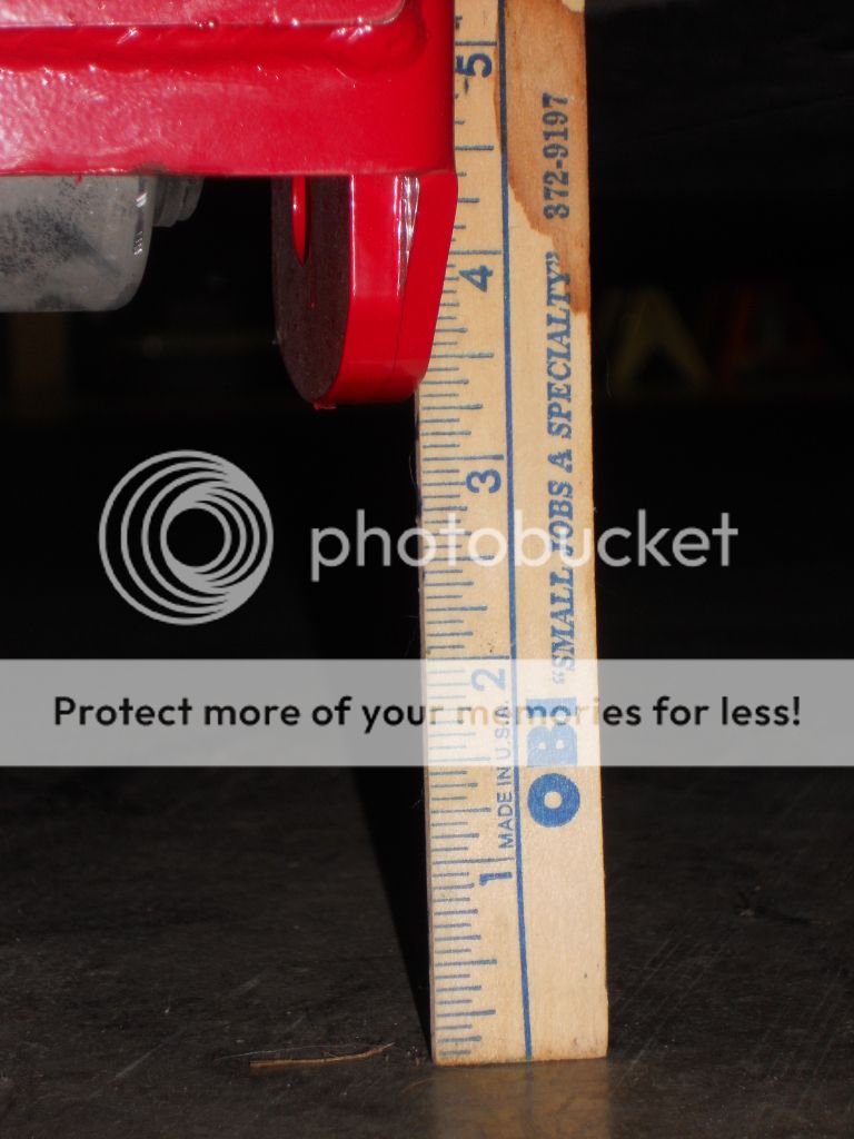
Once the BMR parts went on, it stays dead straight in the rain. Rear tire will spin in the rain, with enough throttle of course, but at least it stays straight. I use the top holes on the BMR relocate brackets. That now puts the LCA's exactly 1" lower at axle end. Before, the oem LCA's were 1" higher at the axle end. That BMR relocate gives you 3 choices. 2"-3"-4" drop. The Roush suspension dropped the rear end by 1".... but the minimum the relocate bracket will do is 2", hence the reason the LCA's are lower at axle end, instead of level. I like em a bit lower anyway. Then you get a LOT better traction in the dry...and wet.

I also used the BMR adjustable UCA and mating BMR UCA mount. ( while all this was being done, we also did the BMR A arm brace ). Zero wheel hop. From a 6 mph roll, I can hammer it in 1st gear, and the 275mm nitto 555's don't break traction, they stick. (390rwhp) Good, this is precisely what I wanted.

Apparently, your brake bias will be shifted a bit to the rear, when the LCA's are lower at axle end, so you don't want to be using the middle or lowest hole. I didn't notice that effect so far.

Jimbo
I had the stock, oem Ford pan hard bar..which is 1" SOLID steel rod....and heavy. It has huge rubber bushings on each end. It's non adjustable. Funny thing is, once the wider rear tires went on, I could see right away that the sidewall was sticking out at least .4" more on the driver's side vs passenger side, and this was BEFORE the rear end was lowered with the roush suspension. Once the Roush suspension was installed, that offset didn't get any worse. (no change). Problem is... now the oem lca's are not only sloping at an angle, they are also offset to one side by .4"..... which will permanently bend em. (they were twisted..and are trashed).

The sequence is to get the BMR adjustable pan hard bar installed asap..1st...and precisely aligned, THEN install everything else. If you don't, you will have a helluva time getting the new LCA's installed if any offset was still there.

I don't believe Roush even makes or equips their cars with adjustable pan hard bars. (mine is a GT) The oem pan hard brace is right above, and parallel to the adjustable pan hard bar. The oem one is junk, it's 3 sided channel steel. That does your side loading. The BMR version uses rectangular tubing, turned up on edge. It's the real deal. " PHR007 - Upper Panhard Rod Support" Part Number: PHR007 http://www.bmrsuspension.com/?page=p...&productid=173

Here is the BMR adjustable pan hard bar I used.... on car adjustable. Part number PHR-006 http://www.bmrsuspension.com/?page=p...&productid=172
If you use a Fays2 watts link, then an adjustable pan hard bar isn't required.

It baffles me how Roush can lower their cars, then "forget" to install the adjustable pan hard bar + brace, relocate brackets for the LCA's, and adjustable camber plates. BTW, I posted a pix of the bmr adjustable pan hard bar + brace + relocate brackets on the 2010-2012 forum, plus the steeda REAR STB.

You require the special synthetic grease + new grease gun for these BMR poly ends. (then no contamination) They all have grease nipples, including the BMR adjustable UCA, boxed LCA's, and both ends of the adjustable pan hard bar (7 in total). They get re-greased after 500 miles, then once per year after. Zero NVH so far.

Jimbo

I spoke with Kelly at BMR and he recommended to keep the ROUSH UCA for now and see what happens with the new transmission/driveshaft. If I get vibration, then I'll be upgrading the UCA.

Also, is this really worth it over the panhard bar setup? http://fays2.net/fays2_watts_link_11_.html
I understand the who articulation advantage and all...but since I am not a professional racer, does it really matter? I read even professional racers still use panhard bars.

This would cost $400 (plus shipping) over a BMR panhard bar setup.

I still have quite a few pages... This was originally over 75 pages long or something like that... lol
Hopefully I'll be able to share all the key technical data that was shared/discussed.
 
Last edited:

AutoXRacer

forum member
Joined
Oct 8, 2009
Posts
2,601
Reaction score
4
Location
Pacific Northwest
BMR LCA relocation brackets are in!!!! Man do they sit low to the ground!!!

DSC07817.jpg


DSC07818.jpg


Steeda 3 Point Brace!! Wish I would have powder coated them in red...at least painted them... lol

DSC07819.jpg


DSC07821.jpg


Passenger side - stock

DSC07823.jpg


Steeda Brace
Passenger
DSC07828.jpg


Driver
DSC07829.jpg


Check out this sign I bought over the weekend... Says it all... sigh

DSC07825.jpg
[/QUOTE]

BMR LCA relocation brackets are in!!!! Man do they sit low to the ground!!!

here's what you get (with a 20" wheel)....

DSCN5177_cu.jpg


DSCN5353.jpg
[/QUOTE]

Just got the Fay2 Watts Link in today... Very nice packaging:

DSC07833.jpg


DSC07834.jpg


DSC07835.jpg


OK, so I got issues installing the Fays2 Watts Link with the Stage 3 rear sway bar... sigh

DSC07836.jpg


DSC07837.jpg


DSC07838.jpg


DSC07839.jpg


DSC07840.jpg


DSC07841.jpg


DSC07842.jpg


Damn, now do I return the Fay2 Watts Link and go back to the panhard bar? Or do I lose the Stage 3 sway bar and find another that works...?
 

AutoXRacer

forum member
Joined
Oct 8, 2009
Posts
2,601
Reaction score
4
Location
Pacific Northwest
Jim Fays just replied to my email saying there is a shorter frame with only 3 adjustment holes... He says that would probably work.

Do I keep the fully adjustable Fays2 Watts frame and buy a new rear sway bar or get the shorter one and keep the Stage 3 sway bar?

____________________________________________________________________________________________________________________-
On another subject, I also got the Steeda G-Brace...

DSC07830.jpg


Which one do you prefer? BMR (red) or the Steeda (black)?

DSC07831.jpg


DSC07832.jpg


The only reason I ordered the Steeda G-Brace is because I think its stronger than the BMR. The BMR has those L brackets that I can't help think will flex during stress.
What do you think?[/QUOTE]

I like the steeda 3 point sub frame connector's. The BMR version is humongous in comparison..and has to be welded in. Download the BMR install sheet. and it appears it's not an easy thing to install, lotsa stuff to remove 1st, to even get em into place. Having said that, most of the reviews on the steeda 3 point sub frame connector's indicate the steeda works a lot better if it also welded (bolted + welded). http://www.steeda.com/store/steeda-t...d-mustang.html Good write up..reviews at the bottom. The steeda looks like a 30-45 min install. The BMR would take a heck of a lot longer than that, hrs on end. http://www.bmrsuspension.com/siteart/install/SFC011.pdf and http://www.bmrsuspension.com/?page=p...&productid=191

OK, how HEAVY are each of the steeda 3 point sub frame connector's. Did you weigh them by chance..or can you at least guesstimate the weight of each of em. I'm guessing the bmr version is 2-3 x the weight of the steeda. If they don't weigh a whole bunch, I would seriously consider them, since they are relatively cheap, and fast to install. They could always be welded after the fact, if required. The benefits for both drag racing + cornering would be a big plus.

As far as the steeda G trac brace vs the BMR A arm brace... I think its a wash. I just had the same BMR A arm brace installed 2 weeks ago. If you can flex it, I would be very surprised. Notice that the BMR brace is bigger diam tubing, and also has that little jog in the middle. The L brackets are flush to the existing A arm mounts. The steeda G trac uses smaller diam tubing..and has those vertical tubes on each end.... which require super long bolts. The BMR uses the oem bolts. In my case, I have the oem K frame....which already comes with the FRPP A arm brace ! (they all do after 2007). The FRPP ties the back ends of the K frame..and is parallel ( and just a few inchs) aft of my BMR brace. The FRPP ties the K frame, but is not directly across the inner A arm bolts like the BMR-Steeda...and vice versa. So I have TWO braces, just mere inchs apart. In your case, you have a new BMR K frame..which probably has a cross member ( or should) to tie the K frame together at the back end. BTW, my BMR A arm brace ( steeda will be the same) ends up just aft of the eng oil drain plug.

I don't remember how thick the L brackets are on the BMR brace. It's made from 90 ksi DOM, and that stuff is almost triple the strength of mild steel. Tig welding wont screw up DOM..since DOM isn't heat treated in the 1st place. That BMR brace is super light..and no doubt the steeda version is too.

Just to add to the confusion, CHE makes their own version of an A arm brace as well. Now it uses both the oem inner A arm bolts + the "just aft" FRPP bolt holes !
http://www.cheperformance.com/prod-176.htm

Jimbo...

Here is the short version of the Watts Frame...this is the one I am getting, but obviously not Shelby blue... lol
I got this picture from the Shelby website. But its the same since Fays is who makes it for Shelby.

S7MA-5649-2.jpg


S7MA-5649-3.jpg


The shorter style frame only has 3 adjustment holes instead of the 6 or so on the regular frame. Seeing how Shelby only offers the short style, maybe there is a reason for it.

I have been reading that the full watts frame does come in contact with the sway bar at full suspension compression...thus why Shelby uses the short style frame.

Thats what I'll be doing...going with the short style frame. I did like the idea of a better, stiffer, rear bar...but I can do that later...

So here are a few more pics...


Steeda sway bar mounts vs stock. Get rid of the stock mounts!!!!!!! Got to give props to DiMora for persuading me to buy them... lol

DSC07843.jpg


DSC07844.jpg


DSC07845.jpg


DSC07846.jpg


DSC07851.jpg


DSC07854.jpg


DSC07855.jpg


And I finally got the k-member a-arms and a-arm brace all bolted up!!!! I went with the Steeda G-Trac Brace since it was a little wider and avoided me to have to drop the k-member and pull the arms with a rachet winch to bring the a-arm mount closer together.

DSC07848.jpg


DSC07850.jpg


DSC07847.jpg


DSC07856.jpg


I just hope that stupid bar does not get in the way of the drain plug on the oil pan... sigh

Next, tackling the front suspension; springs and struts!!! Waiting for the short watts frame to continue with the rear suspension.

It's a good thing that you took pix of the installed steeda sub frame connector's. I just noticed that my BMR REAR tunnel brace ( + mating DS safety loop) uses the same hole on each side as the steeda sub frame connector's !

http://www.bmrsuspension.com/siteart/install/DTB002.pdf Scroll to the colour pix at the bottom, and you will see the installed tunnel brace. It's 33" wide, and the hole at the extreme left + right is what I'm referring too. This BMR pix is flipped 180 degs from autoXracer's pix. The BMR brace is .25" thick..and weighs exactly 7.6 lbs. It's 3" front to back in the middle.....and 8" front to back, midway out on either side. The tabs on the steeda sub frame connector's appear to be apx .125" thick. They can't overlap with the BMR brace, so my proposed 'fix' is to cut a portion of each offending steeda tab off..then weld both the steeda 3 point brace in..and also the BMR brace. Any of these braces will work a LOT better if both bolted + welded.

I'm 100% convinced that between the pair of 3 point steeda braces..AND the BMR tunnel brace, that the combo will really provide the stiffness I'm after.
BTW, the BMR rear tunnel brace ( + DS safety loop) is actually just aft of the mid point of the DS. I don't trust any of these DS's, and the rear tunnel brace + loop is plenty of protection imo. The DS is so short, that even if it sheared at the front end, it isn't going anywhere. There is only aprx 29" of DS sticking forward of the rear BMR brace + loop.

AutoXRacer, since you are planning on huge HP, (read globs of RWTQ) you may want to seriously consider TIG welding those BMR LCA relocate brackets at some point. No sparks flying about with TIG welding.

Although the steeda sub frame connector's provide front to back support, they don't traverse the left-right chasm across the back end of the tunnel. The added weight of the pair of sub frame connector's + tunnel brace is negated by the weight you dump.... by tossing the oem DS. The oem 2 piece DS won't handle your proposed HP anyway.

Jimbo

Got the passenger side spring and strut on!!!! :D

ROUSH Stage 3 spring and strut; I'm still bummed ROUSH no longer offers this setup:

DSC07956.jpg


Stage 3 front springs part number:

DSC07957.jpg


Steeda Sport springs vs ROUSH Stage 3 springs...seems like ROUSH springs are taller:

DSC07958.jpg


Steeda sport springs, Koni Sport adjustable struts, and J&M camber plates.

DSC07959.jpg
 

skwerl

tree hugger
Joined
Aug 6, 2011
Posts
16,197
Reaction score
1,145
Location
central Florida
Good to see this here, Gerald. I'll enjoy reviewing the build again as you give us the consolidated version. Subscribed.
 

BruceH

BBB Big Bore Boss 322
Joined
Sep 13, 2009
Posts
13,801
Reaction score
14
Location
Pacific Northwest
Your top end was starved for oil judging by the cam journals. So you think the thrust bearing went out on it's own or do you think it was starved for oil too and slowly self destructed until it was too late? What did the main and rod bearings look like?
 

Fullboogie

King of the Ski - OG Jr.
Joined
Oct 27, 2008
Posts
8,476
Reaction score
2,874
Location
Houston
Holy crap that's a lot of work and parts - good luck with your build!
 

BruceH

BBB Big Bore Boss 322
Joined
Sep 13, 2009
Posts
13,801
Reaction score
14
Location
Pacific Northwest
Holy crap that's a lot of work and parts - good luck with your build!

If I understand correctly he just copied his build thread from another forum and posted it here because someone asked him to. His car is all done and he drives it.
 

Support us!

Support Us - Become A Supporting Member Today!

Click Here For Details

Sponsor Links

Banner image
Back
Top