I'd like to leave this in tech for a while for technical discussions but expect to put it in DIY later. Enjoy!
------------------------------------------------------------------------
This is my version of the conversion to 4R70W for a 05+ Mustang that started life as a 55R5 automatic car. It’s a manual valve body. I did this write up because most others I have seen were for either a 5 speed car or a car running a stand alone computer for the transmission to make it shift automatically. Believe it or not the manual valve body on an existing auto car is more involved than the others…especially when it comes to wiring. This write-up assumes your old tranny is already removed. Several decisions must be made along this journey: Who will tune the car, who will build the transmission, who will build the converter, and what type shifter do you want among others.
I started the process by speaking initially with Eric Brooks about the tune. He and Justin from VMP both did me a nice startup tune to get things moving. Eric is good friend with Jerry Wrobleski. If you don’t know who that is you don’t know enough about AOD’s and the 4R70W’s because he was on the Ford team of early development of the transmission when it came out in the early 90’s. Eric ask Jerry W for a recommendation for a builder of the 4R70W and Jerry immediately said the only person he would let build one is Darrin at BC automotive. Well that was good enough for me. Besides I was lucky enough to be able to build an 8 rib kit for the guy that owns the fastest Marauder in the world and guess who built the tranny that heavy pig has behind the Procharger and 75 shot? Darrin’s at BC automotive….so I had heard the name before. If you look on some Marauder forums you’ll find him everywhere…and those cars are heavy.
I contracted with Darrin to build me a tranny to hold 900 rwhp (for $1000 less than Lentech wanted). The tranny has the best of everything in it with the beefed up mid shaft and a PA manual valve body with tranny brake. Next, I asked him about a converter and told him I really liked the PI Stallion. To make a long story short, he recommended Chris at Circle D and mentioned that Jerry liked them. I called Chris and he was honest with me and said that PI made a great converter but that the material for the clutches would give up @700rwhp in lockup. I knew this to be true because Adam at ST had smoked his somewhere in the mid 750 range yet it was fine on his wife’s car in the mid 650 range. Chris said he likes the PI converter so much that for $300 he would re-line a PI converter for me. I opted instead of using the 9.5” PI converter to have him build a custom one with in 10 1/4” with the carbon fiber clutches. PI converter has between 84 and 99 Sq inches of clutch surface and the Circle D has 134 -184sq” depending on the options you get. They are known to hold lockup in high HP Lightning’s. So long story short at 600 hp I would not pay the additional $500 for the other converter but at 750 rwhp (expected) I’m not taking any chances. I can’t say enough great things for both Darrin and Chris. Both went the extra mile for me and their customer service is superior.
Also owe a big thanks to Jim at Turbo Horse power as one pipe needed to be changed and he jumped right on it. In fact he’s been terrific for the entire turbo deal and that’s an en tire separate write-up.
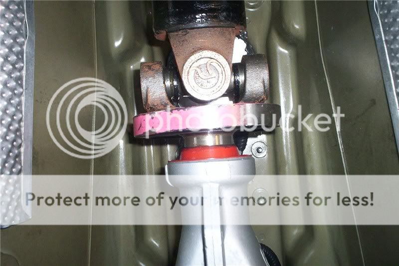
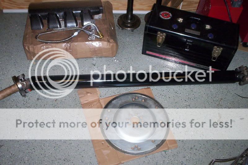
Adam at ST Motorsports had the drive shaft made for me and he too took good care of me (especially when FED EX dropped the first one sent out). The rear flange had to be changed to a pre 2005 flange for an 8.8 rear end. If you decide to build your own you’ll need Ford parts #E9SZ4851A, 1R3Z4841EA, E8VY4782A and bolts N800594S100. Either way you will have to replace the rear flange. The flange used for a spydershaft will not work in case you are wondering.
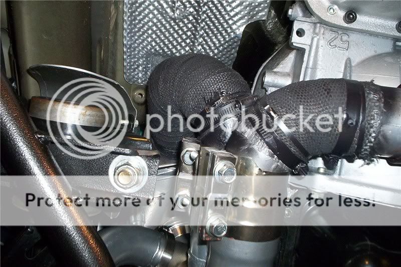
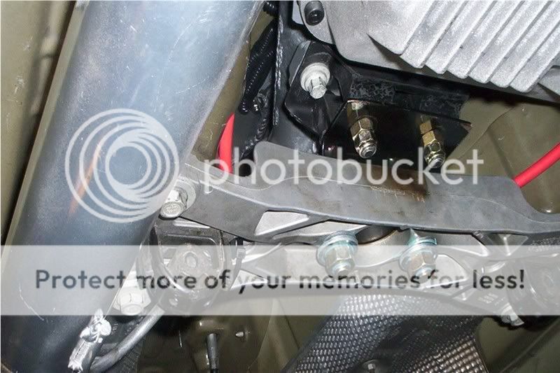
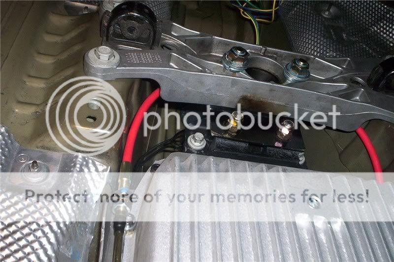
I got a transmission adapter from FB Performance which allowed me to retain the 05
+ Mustang crossmember which is important because my turbo exhaust hangers use the stock locations and will fit back up properly. The 2nd cool thing about it is it restores the proper pinion angle. The adapter kit is a 2 piece kit so be sure you get both the rubber mount and adapter plate.
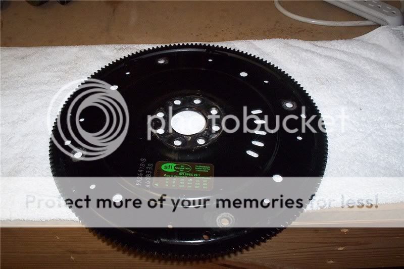
I also got the SFI 8bolt flexplate from them as well. It’s much better construction than the PA flexplate.
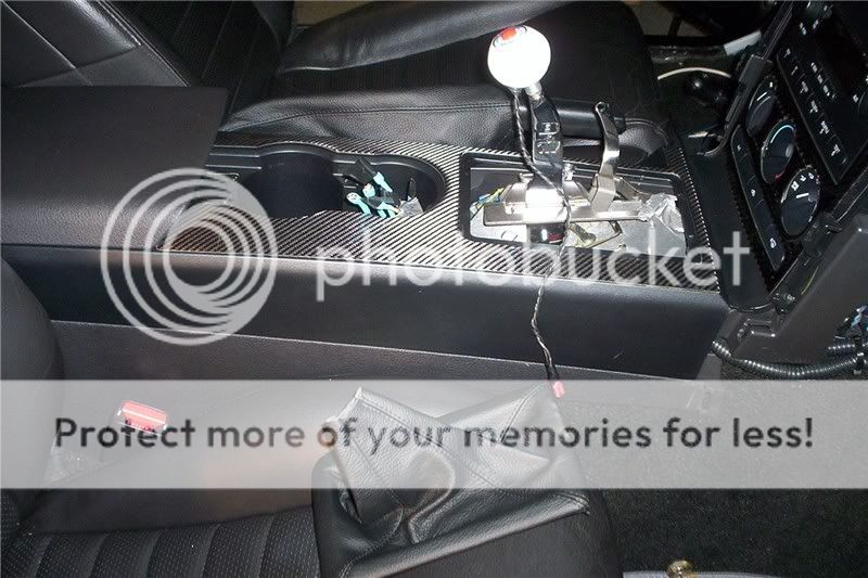
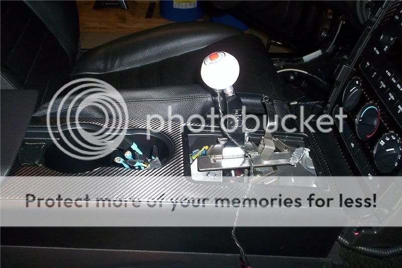
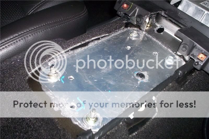
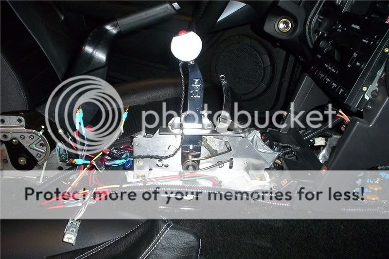
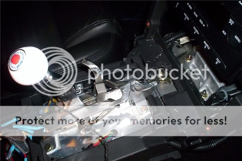
The shifter is a B&M Ratchet. I made a plate of aluminum to cover the stock hole and used 2 of the existing studs to mount the plate along with 2 added holes.
I sealed it up to keep the squirrels out
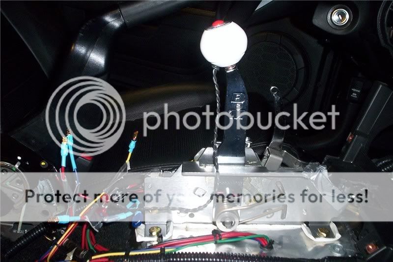
Then I test fitted and mounted the shifter. Part of that process included making a hole for the shifter cable seen in the picture above.
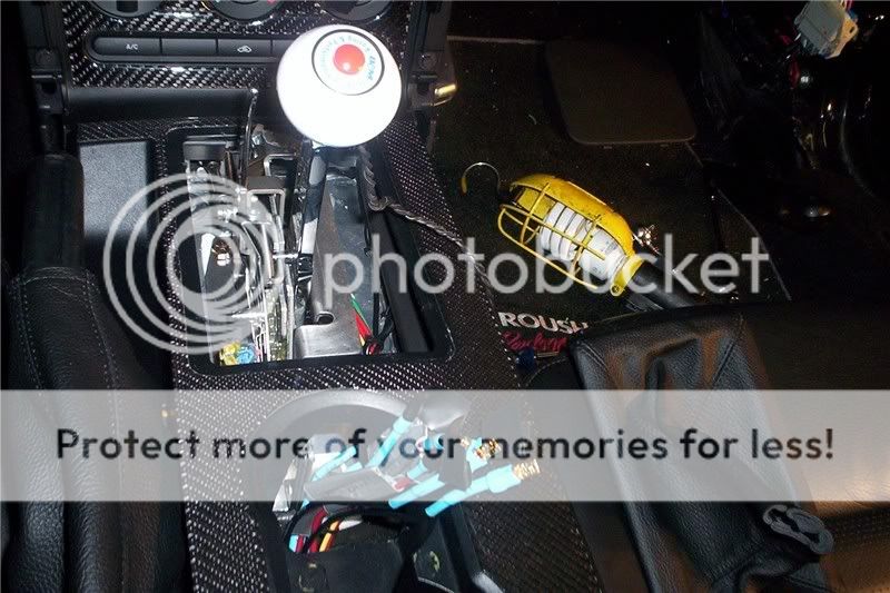
The wiring is a bit detailed. The first thing I did was added a fuse box for those items that could be on a constant hot because they would have their own switch.

Next I drilled a hole in the plate and installed a grommet and ran my wires through for neutral safety, trans brake, lockup, and overdrive. Two of the switches are integral to the shifter; neutral safety and reverse lights.
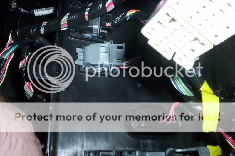
The neutral safety just requires the two wires run up to a switch on the shifter to open and close the circuit. You will get the wires on side of existing transmission… the black box (DRS, range sensor) bolted to the side and use the white/pink wire and red/light blue wires. Those are the neutral safety wires
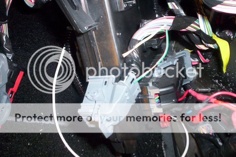
The reverse lights require a power source and that comes from the constant fuse box since the switch will be open except when the shifter is in reverse. On the factory setup these light wires go through 5 sensors so it’s impossible to make the current wiring work. The best you can do is to go to the last spot after the last sensor and provide a 12V source to power them. That requires removing the smart box and finding the wires where they come out and tie them both to one single 12V going to the open switch on the shifter. There is an individual left and right wire for the reverse lights. They are located in connector C2280d, wh/yl and dg/org, pin # 13 and 26. These wires are the output to the lights. Connect one side of your reverse switch to 12v (which you can get in connector C2280a pin# 9 rd/yl) and the other side to both the wh/yl, dg/org. Again you must completely remove the smart box in order to access this plug. Thanks to Mike @ Powerhouse for help on that.
Next is the MSD and tranny brake. I tied those together too because for my purpose I decided I would never use one without the other. They have a constant hot too with an open switch on the shifter button. Press the button and the MSD will hold the RPMs to preset RPMs so the turbo won’t push through the tranny brake and past the converter stall. This can be a problem with a turbo. Let it fly and say goodbye!
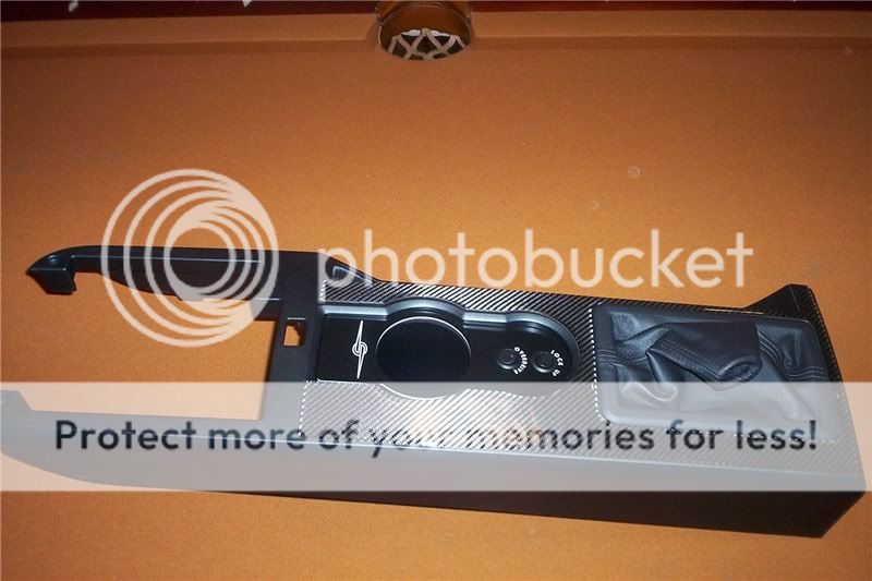
The last two switches I needed are for Lock up and Overdrive. These switches have an LED for reminder. Lockup will be used for 3rd gear at the track and both lock up and overdrive will be used only for highway use. SOS made the cupholder and its different than most. Alan was kind enough to make me a custom plate. The B&M shifter intrudes into the front cupholder so I need to cover that and use it for switches. He did a nice job at a real fair price and did it FAST. Great support!
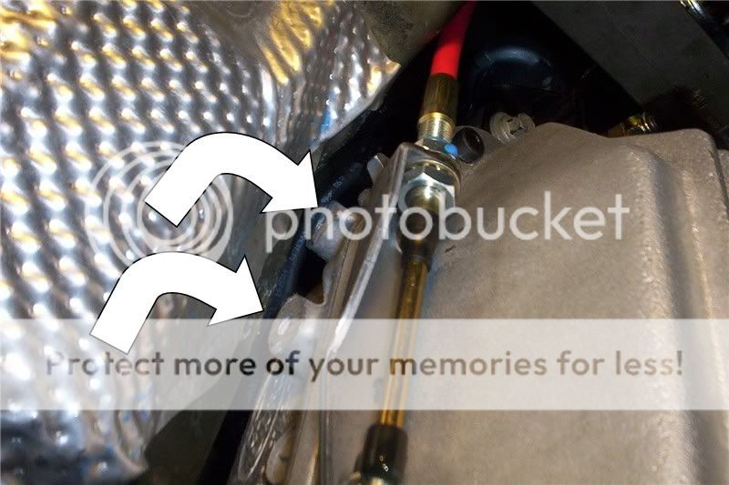
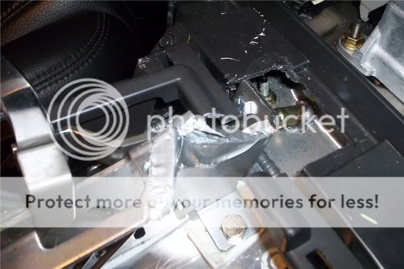
The transmission and tunnel both require some prep work before installation. Two areas of the tunnel need a little massaging. The area adjacent to the shifter linkage and the area adjacent to the fluid line hookups. Some mild taps with a mini maul did the job. The metal is soft and the job is easy.
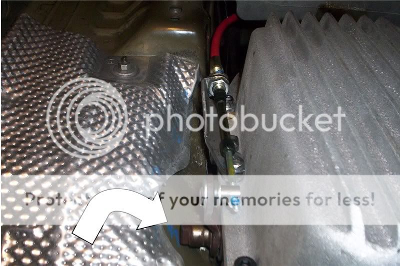
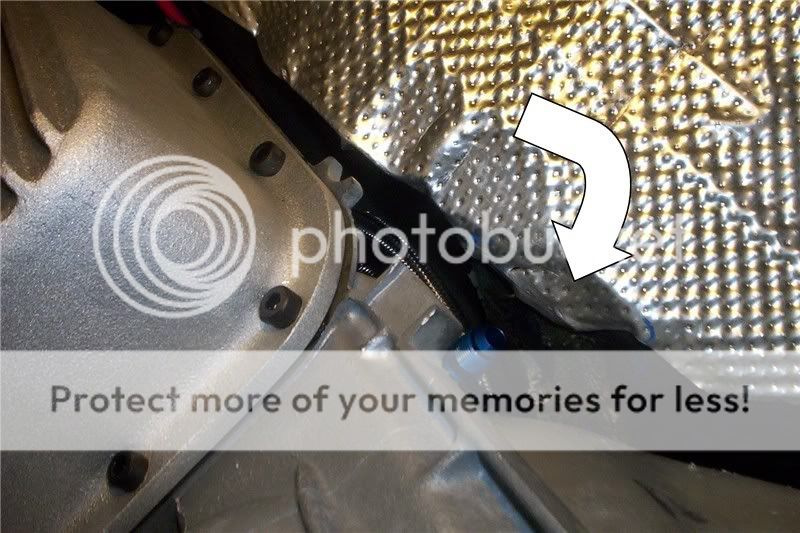
On the transmission there are three casting pieces to cut off; one tab on the passenger side and two lugs on the driver’s side. With the manual valve body none of these are needed (and for that matter are not needed in most other cases either.) Some other applications may need the forward most lug and this would require additional massaging of the tunnel to leave that lug/pedestal in place.
To hook up the speed sensor on the 4R70W you will use the two wires going to the rear most speed sensor on the 55R5. After I found my speed sensor wires, all other factory wires were bundled, taped and tucked up near the top of the transmission bellhousing area and I extended my two speed sensor wires to return them to the 4R70W sensor part#1L3Z7H103AB. In your tune you will need to change the "number of holes in the OSS" to 6 and the speedo will work perfectly.
A few things need to be attached before raising the transmission into place. The speed sensor wire should be connected and the sensor plugged in. There is no room to reach it after the transmission is in place. You may also wish to attach your transmission lines, especially the top one. I replaced my lines with stainless line because I needed to relocate them for the turbo install. At this point it’s worth noting that I have not mentioned an aftermarket transmission cooler. If you are doing this conversion on a previous automatic car, then save your money unless you purchased a non-locking converter. In that case you will want to add a second cooler. But with a locking converter, the factor cooler works fine and has been proven in many cases that I can cite. If you retain the factory lines you will have to get some adapters. I used ¼ npt to -8 AN fittings and then ran -8 lines to the front and tied in to the factory lines. The factory lines are -8 equivalent where the older model mustang uses -6 size lines.
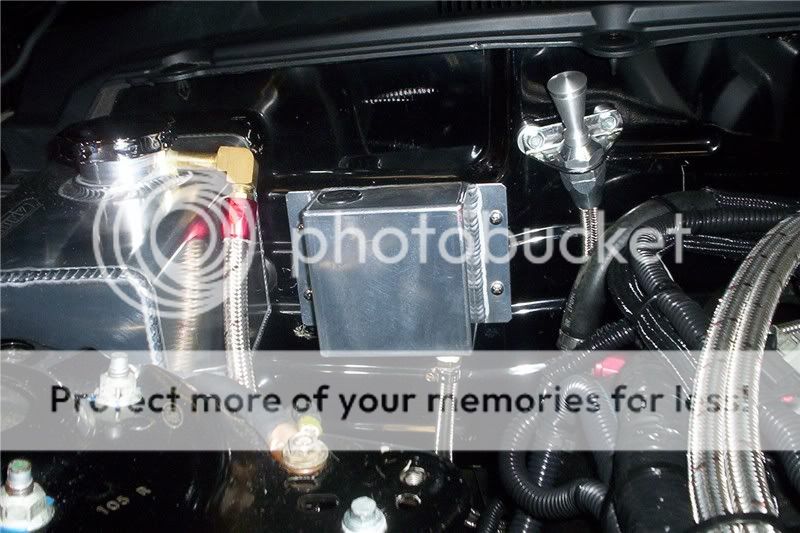
One other thing I chose to do before raising the transmission is to add a breather hose. The 4R70W has a built in breather but I removed the cap from it and added a line and an elbow and ran the line up to my JDM breather box. I had this on the previous setup and wanted to retain it to give lots of room for expansion. The line must be attached before raising the transmission.
While not required at this point I went ahead and connected all my wires and connected the harness plug to the transmission. It can be done afterwards but it’s easier to do now.
Make sure you have attached the entire crossmember/adapter to the tail shaft so you’ll be ready to mount everything when you raise it.
The shifter linkage uses a part provided with the B&M shifter but it must be modified to work. Install cable according to instructions.
The rest is pretty straight forward…
Save some time and mock the flexplate to the converter before installing either and use a marker to mark the proper holes or you’ll be kicking yourself later as you are trying to rote the engine and find them after install.
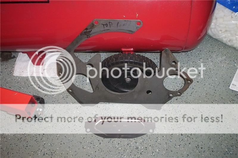
I installed an SFI flexplate (I used a FB performance 8 bolt) using bolts # N606067S439. If you don’t want an SFI plate, run Ford # 4C3Z6375AA. In either case you’ll need the blocking plate/separator plate and dust cover, separator plate XL3Z7007AA, F1VY7986A
Make sure you have put a quart or two of fluid in the converter. Install the converter and remember that as with all Ford trannys you are looking for three distinct clicks to ensure the converter is properly bedded.
Install the transmission. Install the four side bolts. The top two can be reached from under the hood at the back of the intake.
Attach the converter to the holes identified earlier with proper bolts. Use lock-tite.
Install your drive shaft, loop and dipstick. I used the LoKar flexible stick # TD3AODFM. This gave me, well, flexibility needed for the turbo install. You can also use ford # XR3Z-7A228-BA and tube #XR3Z-7A020-BA.
On the inside, I finished the job by adding a leather boot obtained from redline products along with their ebrake cover. An 05 (or applicable year because they are different) five speed GT stock pleather cover will also work. I actually bought that and removed the stock boot and used the frame along with the custom redline product. The stock 5 speed part snaps right into place in the automatic console.
I put the boot on inverted and placed a couple “O”rings over it and lowered it into place.

Finally, I installed the SOS switch plate, my ebrake handle, and ebrake leather bag and called it good.
This project turned out well but takes some time especially the wiring.
A few people I’d like to thank…
Again special thanks to:
Eric Brooks-ModularFords/BrooksSpeed
Darrin-BC Automotive
Justin-VMP Tuning
Jim-Turbo HorsePower
Chris-Circle D
Adam-ST Motorsports
Mike-Powerhouse
Alan-SOS
Regards,
Dave
www.BGGPerformance.com
------------------------------------------------------------------------
This is my version of the conversion to 4R70W for a 05+ Mustang that started life as a 55R5 automatic car. It’s a manual valve body. I did this write up because most others I have seen were for either a 5 speed car or a car running a stand alone computer for the transmission to make it shift automatically. Believe it or not the manual valve body on an existing auto car is more involved than the others…especially when it comes to wiring. This write-up assumes your old tranny is already removed. Several decisions must be made along this journey: Who will tune the car, who will build the transmission, who will build the converter, and what type shifter do you want among others.
I started the process by speaking initially with Eric Brooks about the tune. He and Justin from VMP both did me a nice startup tune to get things moving. Eric is good friend with Jerry Wrobleski. If you don’t know who that is you don’t know enough about AOD’s and the 4R70W’s because he was on the Ford team of early development of the transmission when it came out in the early 90’s. Eric ask Jerry W for a recommendation for a builder of the 4R70W and Jerry immediately said the only person he would let build one is Darrin at BC automotive. Well that was good enough for me. Besides I was lucky enough to be able to build an 8 rib kit for the guy that owns the fastest Marauder in the world and guess who built the tranny that heavy pig has behind the Procharger and 75 shot? Darrin’s at BC automotive….so I had heard the name before. If you look on some Marauder forums you’ll find him everywhere…and those cars are heavy.
I contracted with Darrin to build me a tranny to hold 900 rwhp (for $1000 less than Lentech wanted). The tranny has the best of everything in it with the beefed up mid shaft and a PA manual valve body with tranny brake. Next, I asked him about a converter and told him I really liked the PI Stallion. To make a long story short, he recommended Chris at Circle D and mentioned that Jerry liked them. I called Chris and he was honest with me and said that PI made a great converter but that the material for the clutches would give up @700rwhp in lockup. I knew this to be true because Adam at ST had smoked his somewhere in the mid 750 range yet it was fine on his wife’s car in the mid 650 range. Chris said he likes the PI converter so much that for $300 he would re-line a PI converter for me. I opted instead of using the 9.5” PI converter to have him build a custom one with in 10 1/4” with the carbon fiber clutches. PI converter has between 84 and 99 Sq inches of clutch surface and the Circle D has 134 -184sq” depending on the options you get. They are known to hold lockup in high HP Lightning’s. So long story short at 600 hp I would not pay the additional $500 for the other converter but at 750 rwhp (expected) I’m not taking any chances. I can’t say enough great things for both Darrin and Chris. Both went the extra mile for me and their customer service is superior.
Also owe a big thanks to Jim at Turbo Horse power as one pipe needed to be changed and he jumped right on it. In fact he’s been terrific for the entire turbo deal and that’s an en tire separate write-up.
Adam at ST Motorsports had the drive shaft made for me and he too took good care of me (especially when FED EX dropped the first one sent out). The rear flange had to be changed to a pre 2005 flange for an 8.8 rear end. If you decide to build your own you’ll need Ford parts #E9SZ4851A, 1R3Z4841EA, E8VY4782A and bolts N800594S100. Either way you will have to replace the rear flange. The flange used for a spydershaft will not work in case you are wondering.
I got a transmission adapter from FB Performance which allowed me to retain the 05
+ Mustang crossmember which is important because my turbo exhaust hangers use the stock locations and will fit back up properly. The 2nd cool thing about it is it restores the proper pinion angle. The adapter kit is a 2 piece kit so be sure you get both the rubber mount and adapter plate.
I also got the SFI 8bolt flexplate from them as well. It’s much better construction than the PA flexplate.
The shifter is a B&M Ratchet. I made a plate of aluminum to cover the stock hole and used 2 of the existing studs to mount the plate along with 2 added holes.
I sealed it up to keep the squirrels out
Then I test fitted and mounted the shifter. Part of that process included making a hole for the shifter cable seen in the picture above.
The wiring is a bit detailed. The first thing I did was added a fuse box for those items that could be on a constant hot because they would have their own switch.
Next I drilled a hole in the plate and installed a grommet and ran my wires through for neutral safety, trans brake, lockup, and overdrive. Two of the switches are integral to the shifter; neutral safety and reverse lights.
The neutral safety just requires the two wires run up to a switch on the shifter to open and close the circuit. You will get the wires on side of existing transmission… the black box (DRS, range sensor) bolted to the side and use the white/pink wire and red/light blue wires. Those are the neutral safety wires
The reverse lights require a power source and that comes from the constant fuse box since the switch will be open except when the shifter is in reverse. On the factory setup these light wires go through 5 sensors so it’s impossible to make the current wiring work. The best you can do is to go to the last spot after the last sensor and provide a 12V source to power them. That requires removing the smart box and finding the wires where they come out and tie them both to one single 12V going to the open switch on the shifter. There is an individual left and right wire for the reverse lights. They are located in connector C2280d, wh/yl and dg/org, pin # 13 and 26. These wires are the output to the lights. Connect one side of your reverse switch to 12v (which you can get in connector C2280a pin# 9 rd/yl) and the other side to both the wh/yl, dg/org. Again you must completely remove the smart box in order to access this plug. Thanks to Mike @ Powerhouse for help on that.
Next is the MSD and tranny brake. I tied those together too because for my purpose I decided I would never use one without the other. They have a constant hot too with an open switch on the shifter button. Press the button and the MSD will hold the RPMs to preset RPMs so the turbo won’t push through the tranny brake and past the converter stall. This can be a problem with a turbo. Let it fly and say goodbye!
The last two switches I needed are for Lock up and Overdrive. These switches have an LED for reminder. Lockup will be used for 3rd gear at the track and both lock up and overdrive will be used only for highway use. SOS made the cupholder and its different than most. Alan was kind enough to make me a custom plate. The B&M shifter intrudes into the front cupholder so I need to cover that and use it for switches. He did a nice job at a real fair price and did it FAST. Great support!
The transmission and tunnel both require some prep work before installation. Two areas of the tunnel need a little massaging. The area adjacent to the shifter linkage and the area adjacent to the fluid line hookups. Some mild taps with a mini maul did the job. The metal is soft and the job is easy.
On the transmission there are three casting pieces to cut off; one tab on the passenger side and two lugs on the driver’s side. With the manual valve body none of these are needed (and for that matter are not needed in most other cases either.) Some other applications may need the forward most lug and this would require additional massaging of the tunnel to leave that lug/pedestal in place.
To hook up the speed sensor on the 4R70W you will use the two wires going to the rear most speed sensor on the 55R5. After I found my speed sensor wires, all other factory wires were bundled, taped and tucked up near the top of the transmission bellhousing area and I extended my two speed sensor wires to return them to the 4R70W sensor part#1L3Z7H103AB. In your tune you will need to change the "number of holes in the OSS" to 6 and the speedo will work perfectly.
A few things need to be attached before raising the transmission into place. The speed sensor wire should be connected and the sensor plugged in. There is no room to reach it after the transmission is in place. You may also wish to attach your transmission lines, especially the top one. I replaced my lines with stainless line because I needed to relocate them for the turbo install. At this point it’s worth noting that I have not mentioned an aftermarket transmission cooler. If you are doing this conversion on a previous automatic car, then save your money unless you purchased a non-locking converter. In that case you will want to add a second cooler. But with a locking converter, the factor cooler works fine and has been proven in many cases that I can cite. If you retain the factory lines you will have to get some adapters. I used ¼ npt to -8 AN fittings and then ran -8 lines to the front and tied in to the factory lines. The factory lines are -8 equivalent where the older model mustang uses -6 size lines.
One other thing I chose to do before raising the transmission is to add a breather hose. The 4R70W has a built in breather but I removed the cap from it and added a line and an elbow and ran the line up to my JDM breather box. I had this on the previous setup and wanted to retain it to give lots of room for expansion. The line must be attached before raising the transmission.
While not required at this point I went ahead and connected all my wires and connected the harness plug to the transmission. It can be done afterwards but it’s easier to do now.
Make sure you have attached the entire crossmember/adapter to the tail shaft so you’ll be ready to mount everything when you raise it.
The shifter linkage uses a part provided with the B&M shifter but it must be modified to work. Install cable according to instructions.
The rest is pretty straight forward…
Save some time and mock the flexplate to the converter before installing either and use a marker to mark the proper holes or you’ll be kicking yourself later as you are trying to rote the engine and find them after install.
I installed an SFI flexplate (I used a FB performance 8 bolt) using bolts # N606067S439. If you don’t want an SFI plate, run Ford # 4C3Z6375AA. In either case you’ll need the blocking plate/separator plate and dust cover, separator plate XL3Z7007AA, F1VY7986A
Make sure you have put a quart or two of fluid in the converter. Install the converter and remember that as with all Ford trannys you are looking for three distinct clicks to ensure the converter is properly bedded.
Install the transmission. Install the four side bolts. The top two can be reached from under the hood at the back of the intake.
Attach the converter to the holes identified earlier with proper bolts. Use lock-tite.
Install your drive shaft, loop and dipstick. I used the LoKar flexible stick # TD3AODFM. This gave me, well, flexibility needed for the turbo install. You can also use ford # XR3Z-7A228-BA and tube #XR3Z-7A020-BA.
On the inside, I finished the job by adding a leather boot obtained from redline products along with their ebrake cover. An 05 (or applicable year because they are different) five speed GT stock pleather cover will also work. I actually bought that and removed the stock boot and used the frame along with the custom redline product. The stock 5 speed part snaps right into place in the automatic console.
I put the boot on inverted and placed a couple “O”rings over it and lowered it into place.
Finally, I installed the SOS switch plate, my ebrake handle, and ebrake leather bag and called it good.
This project turned out well but takes some time especially the wiring.
A few people I’d like to thank…
Again special thanks to:
Eric Brooks-ModularFords/BrooksSpeed
Darrin-BC Automotive
Justin-VMP Tuning
Jim-Turbo HorsePower
Chris-Circle D
Adam-ST Motorsports
Mike-Powerhouse
Alan-SOS
Regards,
Dave
www.BGGPerformance.com
Last edited: