Comprehensive IC Water Pump/System Test Data

Pentalab

forum member
Joined
Mar 5, 2013
Posts
5,216
Reaction score
1,104
Good point about the air heating things up. You could probably just block off the front of the HE a bit to assist. Either way it has to be way better flowing say 65 degree water than just worrying about how much water you can pump and then cool down with 80 degree air. If you are at the strip im sure it's a lot cheaper to dump a bag of ice in a trunk tank though. But for everyday use I'm probably going to go with the kc before dropping 450 on a crazy pump. Hmm there is probably a point where you need the cold water to move faster through the intercooler though if you are really heating things up.

KC makes a HE bypass setup, using electric solenoids to bypass the HE completely. Then it's just the KC + IC + pump etc. If you block off the front of the HE, then u also restrict air into the rads behind the HE, like the AC rad, eng rad (+ auto tranny rad if an auto) etc. While ice would work, the pix I saw depicted the (KC equipped) car returning after the run down the strip. By the time he got back, then into the line, behind a few other cars, it had cooled down, ready to go again. If the coolant was between 40-60F (they will easily drop the coolant temp to 40F), I would not bother with a bigger pump (at least not initially). With enough cold coolant in the de-gas jug, you would have plenty of cold coolant for short bursts with the blower on.

I think I have aprx 2 gals in the IC-degas-pump-HE loop. With the little Bosch pump running 4 gpm, that's 30 secs to circulate all the coolant...once. That's plenty for my applications.
 
Last edited:

palanza7

forum member
Joined
Apr 6, 2015
Posts
648
Reaction score
16
Majority of tracks don't want a/c ran at the track. Condensation dripping off the car on the way down and some high HP car hits it

I think I've read they have a track option for this, something that handles the drippage.
 

Pentalab

forum member
Joined
Mar 5, 2013
Posts
5,216
Reaction score
1,104
I think I've read they have a track option for this, something that handles the drippage.

They do, it collects the condensate. Nothing ends up on the ground.Dunno what it ends up in, but presumably it has to be emptied.
 

DiMora

More Is Better
Joined
Aug 22, 2010
Posts
971
Reaction score
41
Location
Fayetteville, GA
I finally got around to installing a regular fleet 12v-25amp version of the WP29 pump I picked up a while back, I spliced in some 1" hose to the existing 3/4" using 1"-to-3/4" schedule 40 barbs.

Good news it only pulls 6.5 amps. Running it and the IC fans together pulls 12 amps. Kinda hard to tell as my old Bosch pump was dying but it looks like it's moving roughly twice what a new Bosch pump would flow.

I bent a piece of 3/16" flat steel bar for the the mount and put it on the passenger side in front of the washer fluid bottle ..

Not the prettiest install but it should work well enough for me.

This is an old thread, but I want to help others (and you if you are still around)...
I am installing mine right now. Your pump is oriented incorrectly. That mounting location is not approved and will result in pump failure per Stewart/EMP due to no weep collection.
 

DiMora

More Is Better
Joined
Aug 22, 2010
Posts
971
Reaction score
41
Location
Fayetteville, GA
Yea im looking forward to the engineering math's for all this shit your coming up with :p

Yea if HE and IC were same size it would get heat soaked quickly and not work well.

good news is we can fit a nice sized HE on the front of our cars :)

I did tell him about the dual HE setup with one in the trunk behind a bulkhead and one in the front, thought it was neat. I think a larger set could be fit and sealed to the wider parts of the trunk and let out the back ;)

Here's your math:

Poiseuille's law (Hagen-Poiseuille equation) is what governs what is going on with our supercharger intercooler systems...it governs fluid flow in a pipe. Don't quit reading when you see the formula below...it is quite easy to understand.

From Wikipedia:


ΔP = 8μLQ / πR4

or

Q = ΔP πR4 / 8Lμ

Where:

ΔP is the pressure difference between the two ends, L is the length of pipe, μ is the dynamic viscosity, Qis the volumetric flow rate, R is the pipe radius.

Here is what it distills down to as it applies to our systems:


  • ΔP (pressure) is going to be directly impacted by what fluid pump we choose and the inlet / outlet diameter of that pump as well as how that pump performs with flow resistance in the rest of the system


  • L (pipe length) is more-or-less "fixed" in our cars; the only impact we can have on that is by routing our hoses "smartly" to avoid excess hose length when not necessary. Perhaps mount the pump as close to the heat exchanger inlet as possible...or as close to the intercooler inlet as possible...the bottom line is avoid excessive plumbing length if not necessary.


  • μ (dynamic viscosity) we have very little control over...we are using water / glycol (antifreeze) and perhaps water-wetter. The higher the viscosity (thicker the fluid) the worse flow rate. Water is thinner than glycol...so using the least amount of glycol for our environmental conditions that we can get away with is best (don't use so little that your intercooling system freezes in winter and you destroy things)


  • Q (volumetric flow rate) is what we are really trying to "solve" for...so all the other parameters in the formula impact Q


  • R (Pipe radius) we *can* control up to some extent...more on this in a second, as you will soon see why that item is the most critical along with pump selection. Here is the most important part of R. Notice in the formula that it is to the 4th power. That means that compared to the other variables, radius of the pipe has the absolute largest impact on our flow rate. Layman's terms points concerning radius:


  1. Fluid in a pipe moves slower near the walls of the pipe and faster in the middle.
  2. For a given original flow rate of a given fluid...the following are true:


  • Double the length of the pipe and the flow rate is cut in half
  • Double the viscosity of the fluid and the flow rate is cut in half
  • Double the system pressure and the flow rate doubles (Pump selection!)
  • Double the pipe radius and the flow rate increases by 16 (Plumbing diameter!)
    • A 19% increase in pipe radius doubles flow rate


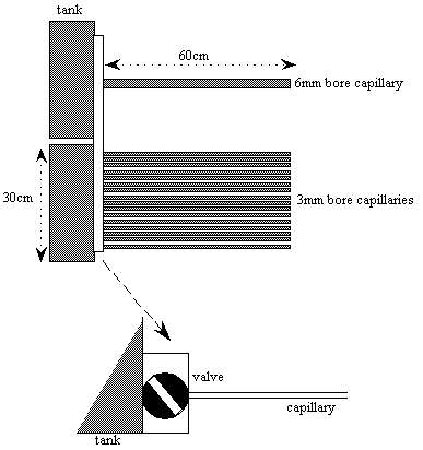
I found this demo online that summarizes this nicely here. Check this out:

poiseuilleslaw004.png

See the two tanks?

The top one with the 6MM drain capillary will empty at the exact same time as the lower one that has 16 3MM bore capillary tubes!

Summary:


  • Choosing the largest diameter plumbing in the system that is possible can increase flow rate. Even if there is a restriction in part of the system that we cannot overcome without replacing the intercooler (3/4" inlet / outlet) decreasing the negative impact of small pipe diameter in the rest of the system should increase overall flow rate by mitigating flow resistance of the coolant at the pipe / hose walls
  • Choosing a pump that flows a high volume and works with with a restriction in the system is critical. As the experiments of others have proven, a pump that flows well with no restriction (Meziere) does not do so well with resistance (20 GPM unrestricted vs. 3 - 3.5 GPM in a restricted 3/4" system)
  • Use the shortest plumbing you can get away with...route hoses wisely
  • Use the least amount of glycol you can get away with based on how cold it gets where you live (impact of this is minor compared to plumbing hose diameter and pump selection)
 

Latest posts

Support us!

Support Us - Become A Supporting Member Today!

Click Here For Details

Sponsor Links

Banner image
Back
Top