Twin Twins

Bobby

turbo gt about to go fast
Joined
Dec 10, 2007
Posts
5,085
Reaction score
2
Location
just out side of charlotte north carolina
Yes two guys make it easier. Mount the turbos and the wastegates to the pipes first. Make sure to leave the vband clamps for the wastegates loose so you can move them and the gates. Once you mount it and get every thing clocked and put where it needs to be then tighten it all down. These are the hardest part of the entire kit.
 

JeremyH

3V Fuel Guru
Joined
Jan 10, 2009
Posts
20,857
Reaction score
206
Location
Virginia Beach
That sucks about the compressor covers looks like they put on the wrong larger CT4 cover vice the CT3 cover. Bobby is calling Comp today to get the correct ones shipped.


One point of pain and challenge for us was the driver side pipe and wastegate and clamp: there isn't enough room to get that clamp on once the pipe is bolted to the turbo flange (maybe we should have put the wastegate on the pipe first, and THEN connected to flange the turbo).
The passenger side wastegate clamps were quick and easy; we knocked that last one out in maybe 5 minutes, from start to stop, once the wastegate springs were put in. Hands and tools were flying, we got it down!

Throughout this part of the installation, it really helped having both of us work on things, especially in trying to get the turbos and pipe connected to the exhaust manifolds. We are doing this on jackstands, but having a lift is the way to go.


Yes install it all first and leave the wastegate clamp loose so you can orient everything like Bobby said and tighten later.

Dont forget to reference the install thread!
http://www.s197forum.com/forum/showthread.php?t=112652

Also any tricks or install tips you guys have let us know and we will add it to the install thread! Pics always help! ;)


So next up it mounting the wastegates and turbine housings to the feed pipes. I will show doing the driver side feed pipe (no 02 bung) first. The easiest way is to remove the turbine housing from the center section of the turbo. To do so remove the 6 14mm bolts and clips from the back of the turbine housing and then slide it off. This makes it easy to mount the turbine to the feed pipe and tighten all the brass nuts.

Shot of the backing plates.

20140414_113614_zpsyxtntprs.jpg


On the driver side feed pipe the wastegate is installed upside down with the exit facing back and the 3"vband outlet on the turbine housing faces back as well. The turbine will only go on this way anyway as the wastgate would be in the way if you mounted it backwards. Install the turbine housing with gasket and fully tighten all the brass nuts. The gaskets will crush and seal so make sure the bolts are torqued down evenly, you can also use some copper rtv sealant to make sure you have a good seal here, I did not use any since there is a gasket, but it wouldn't hurt.

20140412_102616_zpsx92aqxjl.jpg


Next remove the orange tape from the bottom port holding the fire ring in place. Mount the bottom vband port with fire ring to the vband flange for the wastegate on the feed pipe. Slip on the low profile clamp and arrange it so the nut for tightening is facing down/back so it can be fully tighten easily once on the car. Just leave it snug enough so you can still rotate the gate on the flange for best positioning. The nut will be fully tightened later as mentioned.

20140412_104410_zpsuti6la3v.jpg

20140412_104417_zpslgtihwog.jpg


The passenger side pipe has the 02 bung for the front 02 sensor. Using a dab of antiseize on the front 02 sensor threads install and tighten it into the bung on the feed pipe. Then install the turbine housing and wastgate the same way you did on the drivers side pipe. On this pipe the outlet vband on the gate and the turbine housing faces away from the header toward the back of the car. Again position the nut for the wastegate flange down and back so it can be fully tigtened later on the car easily.

20140412_130129_zpsfepkh5lo.jpg


NOTE! The turbine wheels are machined for their turbine housings, it is critical that you install the center section back into its turbine housing and that you dont mix them up! So make sure you mark which is which when you take them apart!
 
Last edited:

TexasBlownV8

Formerly TexasBlownV6
Joined
Apr 4, 2008
Posts
5,019
Reaction score
95
Location
Central Texas
Absolutely we are making mental notes at least on what we have issues with as far as installing things.

The thing about attaching the wastegates to the pipes, the driver side could not be installed loosely; it had to be clamped in tight. Pretty-much same with passenger side. Once the clamps were in position enough to hold the wastegates on, they were tight and will not rotate on the pipe. They are a tight fit, but the driver side was extremely hard to get into place; we probably spent a total of 30 minutes on those alone. It looks like the clamps in our wastegates are a different style than those shown in the instructional writeup, and that may be why they were harder to get into proper position and closed.

Generally, we are following the instructions and looking at the pictures. Again it is more applicable to getting things adjusted, but in getting the orientations of the turbo and water ports (and grease fitting on the turbo if present), and wastegate ports, it was a little hard to know where to put them. Yes we'll need to probably adjust and tweak the turbo rotation, but, will that be adjustable (as far as being able to get a wrench/socket on the bolts) on the larger turbo side or on the smaller flange side of the turbo brackets once it is mounted up into the car?
Also, something we did on Leo's car car was to defer putting in the fittings in the driver-side wastegate air ports until we knew exactly how the wastegate was going to fit into the car. The instructions mention to use a plug on the driver side gate top and vent out the side, but there are no pics about that one (the pics show the the banjo fitting out the top like on the passenger side, and you don't want to do that).
And as far as the wastegate air ports go, the "top-side vent port" depends on orentation on where/how you secure the wastegate cover back on to the wastegate (when installing the springs). I would say there is an optimum orientation for the driver side, for this side vent, so that it can be left open or the banjo fitting put in so that it is not pointing toward the front and will not be susceptible to dirt/water. On passenger, the side port is not used and is plugged.

Generally though, it has been straightforward. There are a lot of parts, but after you start getting things in place, you realize it wasn't as hard as you thought it'd be (assuming you have the right turbos!).

Back to the current issue: regarding the housings, your statement: "NOTE! The turbine wheels are machined for their turbine housings, it is critical that you install the center section back into its turbine housing and that you dont mix them up! So make sure you mark which is which when you take them apart!" has me concerned in what Comp will send as replacements. Hopefully it'll be everything that is right :)
 

JeremyH

3V Fuel Guru
Joined
Jan 10, 2009
Posts
20,857
Reaction score
206
Location
Virginia Beach
Yeah you have better quality clamps, the ones in my pics were the cheap ones which we went away from. Even so it does take some muscle to rotate them ie both hands and leverage to turn it. As long as you orient them correctly its fine it may take a couple mock ups to get it oriented exactly as you want, hopefully my pics help for a rough idea. Like you have noticed this is literally the hardest part of the install but once the turbos and gates are on the feed pipes everything else is alot easier/smoother.

I went through a few mock ups getting it all how I wanted. As for the compressor cover and turbine housing bolts, yes I was able to get to every bolt with a wrench while in the car installed and they were all final tightened while installed. I used normal and rachet wrenches.

I removed the top fitting on the drivers side gate due to it being almost completely upside down and since it just vents to atmosphere. There is only one "side" top port that could be used to leave open or install the open banjo fitting in and then plug the very top cover port as well.

20140610_100818_zpskjeutm0w.jpg

20140610_100757_zpsjlthhrgd.jpg


When I had the wrong turbine housing it seized the wheel completely and I couldnt even move it by hand no matter how hard I tried, it has only happened the one time though, I just want to make sure everyone is aware to prevent potential issues. As for the wheels and housings, I have never had an issue with a compressor cover though. You would know right away if something was off like mentioned. What I would do is spin the wheel by hand with the current cover on and get a feel for how easy it spins then swap the new cover on and make sure there isnt a change. Also try to wobble the wheel a little and make sure there is no contact with the cover inlet.
 
Last edited:

retfr8flyr

The Old One
Joined
Apr 7, 2007
Posts
7,193
Reaction score
108
Location
Providence Forge, VA
Absolutely we are making mental notes at least on what we have issues with as far as installing things.

The thing about attaching the wastegates to the pipes, the driver side could not be installed loosely; it had to be clamped in tight. Pretty-much same with passenger side. Once the clamps were in position enough to hold the wastegates on, they were tight and will not rotate on the pipe. They are a tight fit, but the driver side was extremely hard to get into place; we probably spent a total of 30 minutes on those alone. It looks like the clamps in our wastegates are a different style than those shown in the instructional writeup, and that may be why they were harder to get into proper position and closed.

Generally, we are following the instructions and looking at the pictures. Again it is more applicable to getting things adjusted, but in getting the orientations of the turbo and water ports (and grease fitting on the turbo if present), and wastegate ports, it was a little hard to know where to put them. Yes we'll need to probably adjust and tweak the turbo rotation, but, will that be adjustable (as far as being able to get a wrench/socket on the bolts) on the larger turbo side or on the smaller flange side of the turbo brackets once it is mounted up into the car?
Also, something we did on Leo's car car was to defer putting in the fittings in the driver-side wastegate air ports until we knew exactly how the wastegate was going to fit into the car. The instructions mention to use a plug on the driver side gate top and vent out the side, but there are no pics about that one (the pics show the the banjo fitting out the top like on the passenger side, and you don't want to do that).
And as far as the wastegate air ports go, the "top-side vent port" depends on orentation on where/how you secure the wastegate cover back on to the wastegate (when installing the springs). I would say there is an optimum orientation for the driver side, for this side vent, so that it can be left open or the banjo fitting put in so that it is not pointing toward the front and will not be susceptible to dirt/water. On passenger, the side port is not used and is plugged.

Generally though, it has been straightforward. There are a lot of parts, but after you start getting things in place, you realize it wasn't as hard as you thought it'd be (assuming you have the right turbos!).

Back to the current issue: regarding the housings, your statement: "NOTE! The turbine wheels are machined for their turbine housings, it is critical that you install the center section back into its turbine housing and that you dont mix them up! So make sure you mark which is which when you take them apart!" has me concerned in what Comp will send as replacements. Hopefully it'll be everything that is right :)

That's funny. I sent my center sections back and forth to Comp 4 times and they never mentioned anything about putting them back in the same housings. The last time was for completely new oil cooled center sections, so they were never in any housing previously.
 

JeremyH

3V Fuel Guru
Joined
Jan 10, 2009
Posts
20,857
Reaction score
206
Location
Virginia Beach
Thats not from Comp, thats from me lol

I was putting the turbos back together and one spun freely and the other completely seized the turbine wheel and it would not budge, couldnt figure it out. Finally swapped turbine housings on the turbos and they both spun freely no problem. Believe this is why Greg had issues with his twin setup as well. I remember during the demod the passenger side turbo was very hard to turn by hand, he did remove the turbine housings for coating and believe they may have been swapped. Will it happen everytime, probably not. But defiently something to pay attention to.
 

TexasBlownV8

Formerly TexasBlownV6
Joined
Apr 4, 2008
Posts
5,019
Reaction score
95
Location
Central Texas
Thats not from Comp, thats from me lol

I was putting the turbos back together and one spun freely and the other completely seized the turbine wheel and it would not budge, couldnt figure it out. Finally swapped turbine housings on the turbos and they both spun freely no problem. Believe this is why Greg had issues with his twin setup as well. I remember during the demod the passenger side turbo was very hard to turn by hand, he did remove the turbine housings for coating and believe they may have been swapped. Will it happen everytime, probably not. But defiently something to pay attention to.

Well, it's good practice to keep them with their respective other parts. Easy to do while putting things together, so it is good advice anyways.
:hi:
 

FAST3V

Member
Joined
Oct 26, 2010
Posts
731
Reaction score
1
Location
Austin, TX
Mikes slammed with work this week, so postponed till next week yall.
 
Last edited:

TexasBlownV8

Formerly TexasBlownV6
Joined
Apr 4, 2008
Posts
5,019
Reaction score
95
Location
Central Texas
We finally were able to hit it again today. The proper turbo housings came in earlier in the week, and I put those on yesterday.

Before I get started, let me just say that I have a 4r70 transmission in the car, and it is far bigger than a 3650 or 6060, and as such, I expect there to be tighter fitment and may need some alterations to make things fit.
Also, one of my requirements during this process is ensuring I am able to service the transmission (i.e. remove the pan) without having the remove the turbos; I may have to remove the driver-side exhaust pipe to get to the shifter cable and bracket, but that is acceptable.

Today the plan was to get my hot side mounted or at least ready to go, with minimal remaining alterations. I've run into some clearance issues with my 4r70, and needed to do a little "material removal" in a couple places on the transmission housing. After a little grinding and test fitment, we could see where the turbo should sit and be mounted, and tried to fit up the exhaust pipe to the turbo; I have concerns where the two meet regarding clearance for the shifter lever and bolt on the transmission, so wanted to connect it up and get it aligned right. Well, the pipes didn't fit right (angles are off, very obvious), so I couldn't get them connected. But also, It seems that I might need to move the entire assembly forward a little, to give the room needed for the shifter lever, or angle it all a little differently. A small change in the downpipe from the manifold will likely be needed to get things where they will sit and clear everything just fine (or, the flange on the pipe is not correct as it sits and does not properly mate up with the exhaust manifold), and then the exhaust pipe will have to be modified to fit.

Next we tried the passenger side. Well, there's a couple things sticking out that will need to be removed to give the pipe more room, so we didn't get very far in figuring out exactly how close or far off we are. But, I can already tell, there is an issue with the O2 sensor bung and how it does not line up where it needs to be, assuming the turbos will otherwise bolt up where it will need to go. Again though, I need to do a little grinding on the trans to make a little room.

We then moved on to doing the same fitments on Leo's car, starting with the passenger side. After monkeying around with it, and getting things aligned where the exhaust pipe would line up, it was clear that there was an issue with the exhaust manifold flange, in that it will not seal up/sit properly where the turbo should sit; if the turbo is put into a position so that the flange sits right, the inlet of the turbo will be clear the k-member, not by a long shot. But, putting the turbo where it should go, according to the pics, and aligning the exhaust pipe with it, we clearly have an issue at the exhaust manifold connection (bad angle for proper fitment).
OK, so we try the driver side. Zip bam boom, fits right up in there, flange fits great, good and uniform fit. Perfect! Then we put up the exhaust pipe to it; the angle on the end is way off, will not fit, not even close. Then we realize, it's about the same as it was on my car. OK so that pipe end wont work and has to be repaired.

So we then start to think and compare pipes, shapes, ends, angles, etc, and realize that everything may things are different, ever so slightly, but enough to see, and with fitment as critical as it is in many places, things are off enough to make proper fitment impossible. This is where having 2 sets of everything is, once again, really helping up. We laid the exhaust pipes side by side, holding them at the same angles in relation to each other, so that we could compare bends and, more importantly, the angles of the inlet flanges. They are quite different, enough so that one pipe definitely wont fit, and the other one might not fit either (although, one of the passenger pipes seemed to align close on Leo's car, but we can't be sure yet).
We then compared the pipes connecting to the exhaust manifolds. Again, both sides different from each other. We know that the driver-side pipe on Leo's car is right, at least for his car, and comparing it to mine, the flange at the manifold on mine is at a different angle, which we saw when trying to fit it up. For passenger side, Leo's we know is off, and mine is at a different angle so it might be ok, don't know; but also, the O2 bungs are in different positions on that pipe, in the area where fitment is close as it is; the bung it mine may be so far off that it can't be used as-is.

We can understand if something does not fit right not alight perfectly on my car, that was expected to be a possibility going into this project. But there is no excuse for why things don't fit Leo's car perfectly and bolt right in place. THAT is what's really sad here.

No doubt we'll get it straightened out and resolved; things will fit, there is room; but the piping must be precise for everything to fit and bolt up properly, and we're not seeing that in some of the pieces right now.

We don't really know if we're putting things in the right place, but after working with the driver side on Leo's car and seeing how well the downpipe flange and angle matched up to the exhaust manifold, when things fit right (and there's room, which there is in most cars), things fall into place quickly and easily. We are not going to force something at an angle where fitment is not right, or where a massive exhaust leak could occur simply because the flange angle is wrong. These will be installed properly. When done, these will be kick-ass setups, no doubt! But in the meantime, we struggle getting the hot-side into place.

Pics:
- clearancing the bottom lip on driver side of trans housing:
transgriding-driver1.jpg


fits better now:
turbotransclearance.jpg


turbine outlet is a little close to the trans, and may interfere with the shifter (of course I could use a shorter pin on the shifter, and may need to):
turbineout_shiflterlinkage.jpg


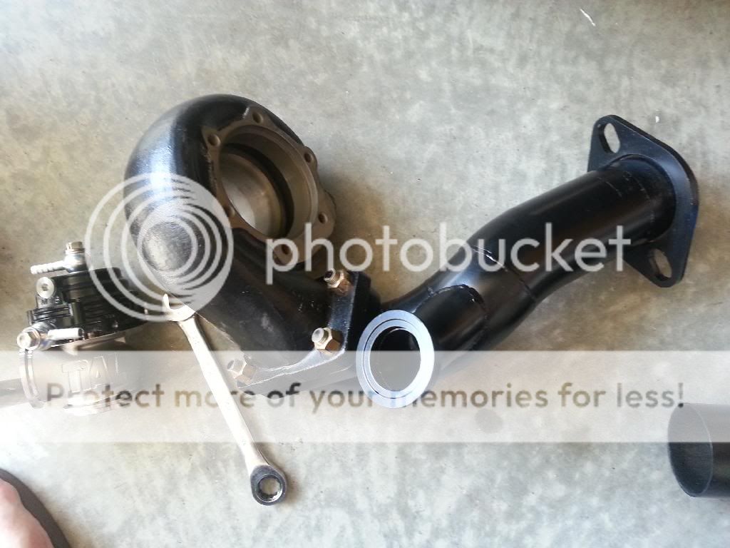
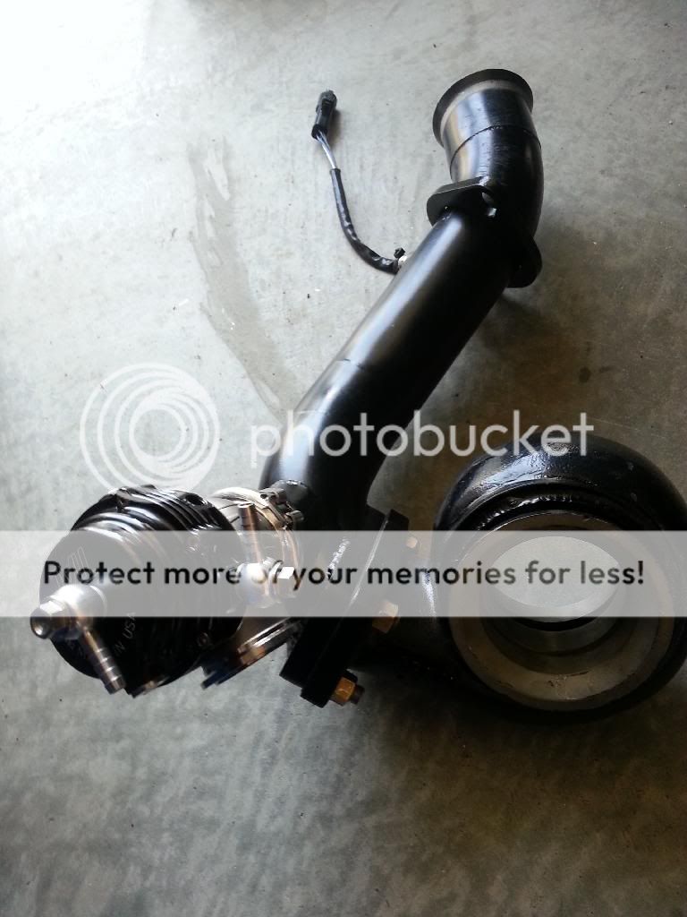
Examples of driver-side exhaust outlet section-to-turbine-outlet, flange-to-flange connection alignment angle issues. These are on Leo's car, but there were very similar issues on mine; these are more of the "closer-fitting" angles, or where pipes should otherwise run and lay in place:
leo_driver_exhaust_nofit.jpg

leo_driver_exhaust_nofit2.jpg


this one may seem a little extreme, but, that's the way it is; the turbo can be raised up some, but not that much to mate up to the pipe:
leo_driver_exhaust_nofit3.jpg


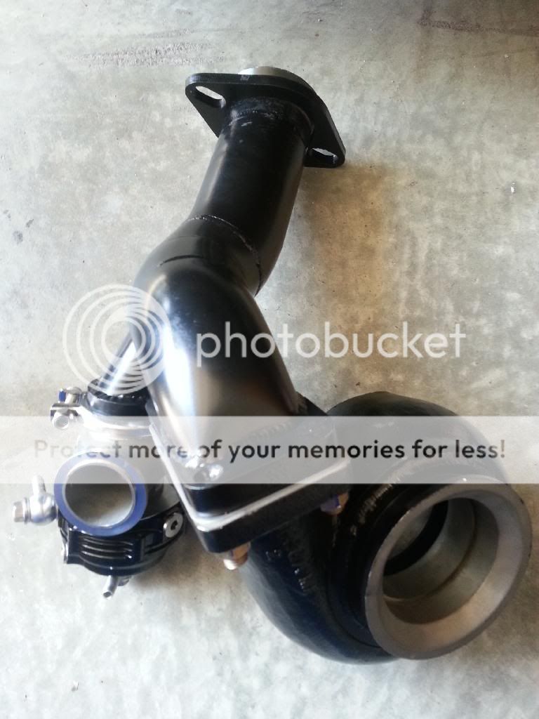
closer comparison of the two driver-side exhaust pipes: even these are put together different from each other, just looking at the pieces welded together. But look at the flange faces more than anything; and these are the best/closest to getting them parallel with each other!:
(this first one really shows how different the two ends are:)
exhpipes_compare1.jpg

exhpipes_compare2.jpg

exhpipes_compare3.jpg


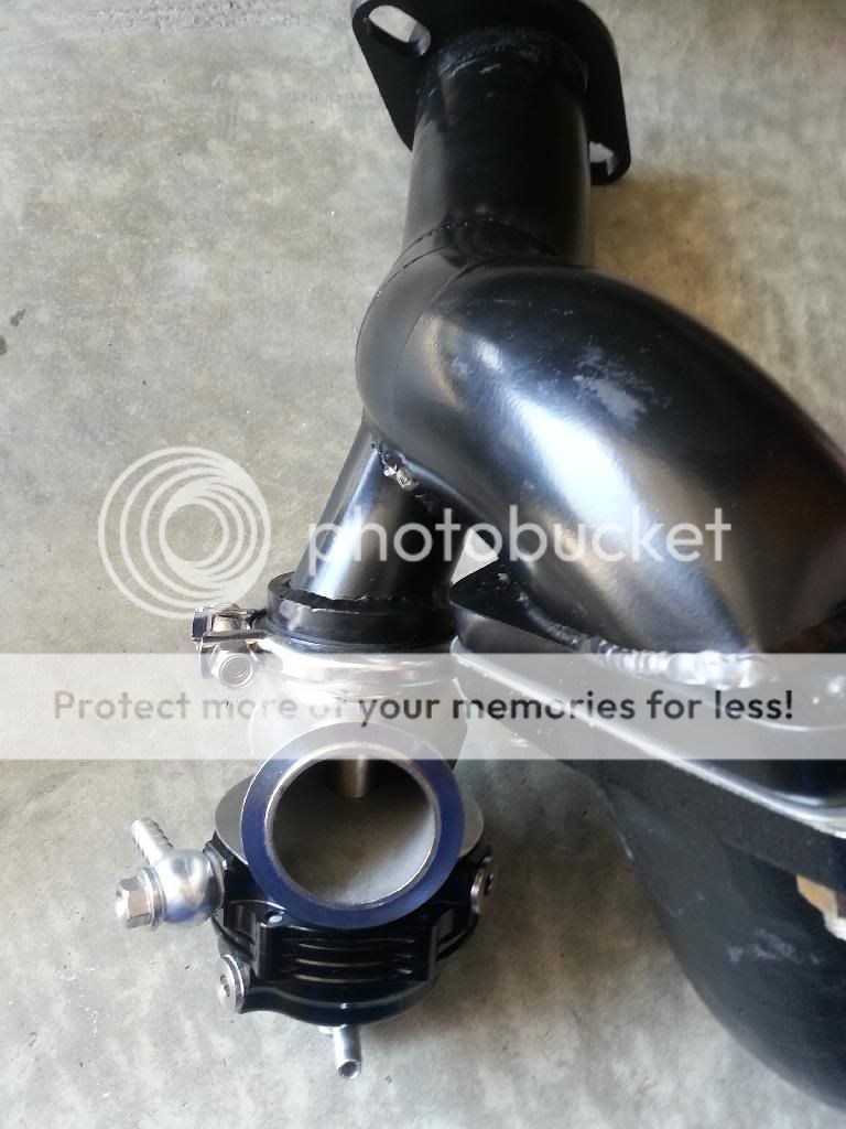
passenger side downpipe from manifolds. The one I'm pointing to is from my car; Leo's is way off on the flared flange. The turbo assemblies and pipes are sitting nearly identical, and the angle of the pic shows how different the flange-end is from each other: you can see the inside of the one I'm pointing to, yet the other one is angled differently. The O2 bungs are located in different positions, too (the one I pointed to may not work at all where it is located). Look at the "ring" on the left one; that is where fitment was reasonable (on Leo's car), and indicates how far off-center that end is from where it needs to be.
psgrdownpipecompare.jpg


that's where we are right now.
 
Last edited:

Bobby

turbo gt about to go fast
Joined
Dec 10, 2007
Posts
5,085
Reaction score
2
Location
just out side of charlotte north carolina
I think once you get the vbands on the down pipe and the turbine housing everything it start to fall in place. I remember when i put my kit back on my car it looked the same but once we did the down pipes and moved the turbo where it needs to be the rest fell into place. Also i spoke with my fab guy. He said that they will not be exact even through it was made in the same jig. He cuts pre bent pipes and doesnt have the exact same bends from one kit to the other. Even though they use different bends they were both made in the jig and ended up in the same place.
 

one eyed willy

Pizzle fo shizzle
Joined
Jul 1, 2008
Posts
7,533
Reaction score
26
Location
Lakeland FL
Turbo piping can be a real bitch, every single pipe changes all the angles for all the rest of the pipes. You can have all but 1 pipe perfectly lined up and the last pipe will not fit.....then you have to start all over again on the rest of the pipes. Hopefully you get it all figured out.
 

TexasBlownV8

Formerly TexasBlownV6
Joined
Apr 4, 2008
Posts
5,019
Reaction score
95
Location
Central Texas
We would have connected up what we could, with the v-band clamps, but we couldn't find them. That's what we were trying to do: get it together, move it all around, and line up everything. Kind of hard to do without clamps.
We know everything is a tight a close it, and it should fit, once things are in their proper places. But when the ends of pipes are at different angles from each other, well, they are not put together the same. It is understandable that different lengths and pieces are used to get the proper bends and such, but the ends have to be perfect to get it all right. And, we don't know if we are running into those kinds of issues, but it sure seems like we are!
Those cats dont give any sideways-wiggle-room if they are to fit in place, and that makes it even more critical for exact mating of components.
 

FAST3V

Member
Joined
Oct 26, 2010
Posts
731
Reaction score
1
Location
Austin, TX
With the way everything appears to be..it's upsetting. The piping having different bends/lengths etc.. isn't concerning..but the way the flanges/ends are pointed seems huge. Especially in cases where one may point straight and the other points to the left. Mike covered everything pretty well, and I don't need to repeat it....but,
I'm going to give the benefit of the doubt & wait until the clamps come in to see how that works out (because that was our original plan)...but I have concern still based on the amount of time we spent playing around with it. At the end of the day the piping with the cut-outs in it that attach to the turbo have to fit perfectly for the clamp to lock-in...and if the angle is off, I'm screwed. Could it be made to work? Maybe, but with an exhaust leak would be unacceptable.
Bobby, please make sure I get the timing cover before Thursday. If I need to pay more in shipping, I will..but didn't realize it would be this kind of turn around.
 

v8venomgt

Senior Member
Joined
Jul 13, 2008
Posts
1,557
Reaction score
3
Location
round lake, il
Yikes, I've been following this closely. I'll reserve speculation till there's resolution. For what the kit costs, you shouldnt have to pump more money into it and hopefully that's not the case. Good luck sorting it all out. Aftermarket turbo components can be a bear regardless so hopefully its just the *teething* period before it all comes together. Good luck.
 

Timmbo

Senior Member
Joined
Jan 17, 2011
Posts
2,067
Reaction score
0
Location
TN
What I don't get is that if this is all done on a jig, there should not be any variation at all between kits. Especially when you have two kits that were built back to back. That's pretty concerning.
 

JeremyH

3V Fuel Guru
Joined
Jan 10, 2009
Posts
20,857
Reaction score
206
Location
Virginia Beach
With the way everything appears to be..it's upsetting. The piping having different bends/lengths etc.. isn't concerning..but the way the flanges/ends are pointed seems huge. Especially in cases where one may point straight and the other points to the left. Mike covered everything pretty well, and I don't need to repeat it....but,
I'm going to give the benefit of the doubt & wait until the clamps come in to see how that works out (because that was our original plan)...but I have concern still based on the amount of time we spent playing around with it. At the end of the day the piping with the cut-outs in it that attach to the turbo have to fit perfectly for the clamp to lock-in...and if the angle is off, I'm screwed. Could it be made to work? Maybe, but with an exhaust leak would be unacceptable.
Bobby, please make sure I get the timing cover before Thursday. If I need to pay more in shipping, I will..but didn't realize it would be this kind of turn around.

The angles of the pipe in areas between flanges will differ slightly as its hand built in a jig so laying them side by side parallel you will see differenes. If you think something is off you can lay one on top of the other and line up the v-band inlet and then the outlet all the way on the other end and compare those that will tell you for sure. Like you mentioned that passenger side seems like its not gonna line up until you get the vband on, then it forces the turbo into the right place. Bobby went through it and when I installed mine I noticed the same thing at first the angles weren't lining up and swore it wasn't gonna fit. This is the hardest part of it guys and everything is very tight here to maximize ground clearance.

Also you do have to notch the passenger side k member to get the turbo into the right place otherwise the downpipe will never line up so if you haven't done that yet go ahead and do so while the v-band clamps are coming.

If something really does not line up in the end, we will take care of it, there is a higher chance of that happening as the pipe was built first in the jig and then had to be modified to fit the cats yall wanted afterwards. Once the vbands are on loosely you can rotate the pipe for best fitment. The cats may need clearanced to fit as well.

Leo, give Bobby a shout he has stuff to send you and is gonna throw the Vbands in with it.
 
Last edited:

FAST3V

Member
Joined
Oct 26, 2010
Posts
731
Reaction score
1
Location
Austin, TX
kk..and like I said..I got the benefit of the doubt going on right now and def think having the clamps will answer everything.
 

TexasBlownV8

Formerly TexasBlownV6
Joined
Apr 4, 2008
Posts
5,019
Reaction score
95
Location
Central Texas
If you think something is off you can lay one on top of the other and line up the v-band inlet and then the outlet all the way on the other end and compare those that will tell you for sure.

We did this, and is how we determined something is not right: the v-band inlets ARE at different angles.

Also you do have to notch the passenger side k member to get the turbo into the right place otherwise the downpipe will never line up so if you haven't done that yet go ahead and do so while the v-band clamps are coming.

We are aware of this, but have not done it yet, as we wanted to see exactly how much notching will be needed. But we also know that the amount should be minimal, and not half of the k member mount!


If something really does not line up in the end, we will take care of it, there is a higher chance of that happening as the pipe was built first in the jig and then had to be modified to fit the cats yall wanted afterwards. Once the vbands are on loosely you can rotate the pipe for best fitment. The cats may need clearanced to fit as well.

We know things will get taken care of. And I agree that the cats, especially where they are and their size, can contribute to some angle issues. But, both pipes should be off the same, same angles on the v-band end; but they are different between each other!

Leo, give Bobby a shout he has stuff to send you and is gonna throw the Vbands in with it.

*** I need these vband clamps right away. ***
Just an idea, would a chain auto parts store have them? I could get one for now, which will help me get mine lined up and in place.
 

retfr8flyr

The Old One
Joined
Apr 7, 2007
Posts
7,193
Reaction score
108
Location
Providence Forge, VA
I think once you get the vbands on the down pipe and the turbine housing everything it start to fall in place. I remember when i put my kit back on my car it looked the same but once we did the down pipes and moved the turbo where it needs to be the rest fell into place. Also i spoke with my fab guy. He said that they will not be exact even through it was made in the same jig. He cuts pre bent pipes and doesnt have the exact same bends from one kit to the other. Even though they use different bends they were both made in the jig and ended up in the same place.

Bobby and Jeremy, I think you guys need to rethink the way your guy is doing the piping on these kits. He should be using the exact same sections from the pre bent pipes to make each pipe, so that the pipes not only fit properly but look identical. I know it's all supposed to be on the same jig but looking at the pics of those 2 pipes there just doesn't seem to be any way they will fit the same from the flange back, as the angles look very different. Doing it this way, if someone down the road needs a replacement pipe, for some reason, they can get one that is exactly the same as the one they had.
 
Last edited:

Latest posts

Support us!

Support Us - Become A Supporting Member Today!

Click Here For Details

Back
Top