Cooling Fan High Speed Relay BEC melted

Morereps

Junior Member
Joined
Jun 27, 2017
Posts
6
Reaction score
0
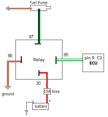
Would this be the correct way to wire the relay? The Hi wire is gr/violet and the Lo is DB. These two wires are located under the BEC in the block closes to the fire wall which is yellow in color. Would this be accurate for those who have done this? F509F3DC-8797-4A78-95CE-19D02F313FB7.gif
 
Last edited:

Morereps

Junior Member
Joined
Jun 27, 2017
Posts
6
Reaction score
0
Would this be the correct way?upload_2020-11-6_0-13-29.png If this isn’t correct, could you email me the the correct way to achieve this? I would greatly appreciate it. My email is [email protected]. I can pay you if you would like payment for your knowledge.
 
Last edited:

sportinawoody

!@#$%^&*(
Joined
Aug 10, 2008
Posts
2,376
Reaction score
36
Location
Piedmont area , N.C.
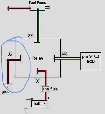
the trigger from ecu is a ground. what does ground need to complete a circuit ? power aka 12volts. you should have one battery source fused, other side to your fan resistor. the switched side of the relay needs ignition on power, and the ecm wire to the other side since that provides ground and turns the relay on, THENNNNNNN, BAMMMM, 12 volts from your battery supplied larger gauge wire, is supplied to your fan resistor and viola!!!! let there be wind
 

Morereps

Junior Member
Joined
Jun 27, 2017
Posts
6
Reaction score
0
Ok I got you! Thanks for your help and your patience. I greatly appreciate it... Sportinawoody you rock!
 

sportinawoody

!@#$%^&*(
Joined
Aug 10, 2008
Posts
2,376
Reaction score
36
Location
Piedmont area , N.C.
everything is right except the circled blue should be ignition switched voltage and this should be your small gauge wire side and obviously that load side(large gauge wire) marked fuel pump, should be to one side of your fan resistor. Hi or lo. 2 relays should be wired in, one for lo one for hi and ecm activates one of these circuits for a/c also so no need to go digging there


19616114-B760-4386-9EA3-67CF6EA5CAA0.jpeg
 

Morereps

Junior Member
Joined
Jun 27, 2017
Posts
6
Reaction score
0
everything is right except the circled blue should be ignition switched voltage and this should be your small gauge wire side and obviously that load side(large gauge wire) marked fuel pump, should be to one side of your fan resistor. Hi or lo. 2 relays should be wired in, one for lo one for hi and ecm activates one of these circuits for a/c also so no need to go digging there


View attachment 74982
Ok cool!!! Now I just have to find ignition switched voltage in the engine bay.....lol Thanks again sir.
 
Last edited:

Morereps

Junior Member
Joined
Jun 27, 2017
Posts
6
Reaction score
0
everything is right except the circled blue should be ignition switched voltage and this should be your small gauge wire side and obviously that load side(large gauge wire) marked fuel pump, should be to one side of your fan resistor. Hi or lo. 2 relays should be wired in, one for lo one for hi and ecm activates one of these circuits for a/c also so no need to go digging there


View attachment 74982


Success!!!!!!! Everything worked out perfectly. I successfully wired both Hi and Low speeds to external relays! Thanks for all the helpful information and hats of the you again sir.
 

Awad Alibrahim

Junior Member
Joined
Mar 12, 2020
Posts
20
Reaction score
2
Location
Saudi Arabia
everything is right except the circled blue should be ignition switched voltage and this should be your small gauge wire side and obviously that load side(large gauge wire) marked fuel pump, should be to one side of your fan resistor. Hi or lo. 2 relays should be wired in, one for lo one for hi and ecm activates one of these circuits for a/c also so no need to go digging there


View attachment 74982
I know it's been a while since this forum has had any activity, but I have a question regarding the ignition voltage. How much does it have to be exactly? Is 12V enough? Also, will air conditioning work directly with this wiring or do I have to add an extra circuit? Because I hooked up the relays externally to check if the fans worked, they did but the AC compressor wouldn't trigger. However I still have to connect the fans in this way. I am just asking so that I can buy any extra necessary things.
 

DieHarder

Senior Member
Joined
Nov 9, 2019
Posts
1,467
Reaction score
758
Engine must be running. AC circuit is separate from the fan but provides a trigger to turn the fan on when AC is activated. The moment you turn on the A/C (via the button/switch) the radiator fan should spin (unless already on at low/high speed) and stay on until the AC is turned off. If it doesn't you need to determine why. Output from the alternator (measured across the batt) should be around ~14v with the engine running.
 

Support us!

Support Us - Become A Supporting Member Today!

Click Here For Details

Sponsor Links

Banner image
Back
Top