Lunati VooDoo #21270700 Camshafts

MrBhp

Senior Member
Joined
Sep 12, 2013
Posts
1,255
Reaction score
1,038
It was really nice being able to set up a 9 inch on the bench. I had a couple different ones for different uses. It was also a lot of fun making the old yards, before they were paid to crush everything. I remember how exciting it was to crawl up under an old Fairlane,Torino etc., and scrape the diff tag to find "3.70L". Score! And then nearly piss yourself when you uncovered the "N" on the carrier. No need for all that anymore.
 

GlassTop09

Senior Member
Joined
May 24, 2019
Posts
1,145
Reaction score
526
Location
Farmington, NM
FYI.......

Should be getting my Stang back in Thursday to make the backlash corrections after checking the pinion preload 1st to ensure that this is still good.....by all accounts it still should be (set this using JEGS solid spacer kit instead of crush sleeve at new bearing setting of 25 in\lbs using Motive 8.8" bearing kit...Koyo M802048-N inner pinion bearing\M802011-N inner pinion bearing race.....) still in the ball park as I parked her as soon as I saw that it wasn't getting any better within the 1st 12 mi of varying low MPH run speeds to save the gears & make recovery easier.....

Yes I know Ford Performance bearing kit uses Timken version bearings (what I used w\ the FP 3.73's) but I wanted to try these to see how they fared since I've never ran Koyo's......always used Timken bearings in the past...........
 

GlassTop09

Senior Member
Joined
May 24, 2019
Posts
1,145
Reaction score
526
Location
Farmington, NM
Update:

Got all reset properly this round so pinion depth\BL settings are within Richmond's specs so all this is good. Ran test on this Richmond EXCEL 3.89 ratio & found it to be a semi-hunting gear ratio that, because of divisor pairing between pinion\ring gear tooth counts being too close to each other, it acts like a non-hunting gear set thus is noisy due to mis-matched\mis-timed lapped tooth pairings. Has nothing to do w\ pinion depth\BL settings if they're set correctly.

I explain all this in detail in this thread: Ford 8.8" Gear Teeth Cut Process Differences That Affect Setup | S197 Mustang Forum - S197Forum.com post #15.

This is not necessarily a deal breaker (at least for me it isn't at this time) but this gear set has to be broken in in a specific manner to allow the pinion\ring gear teeth to wear in to the new timed pairings (manuf should have inscribed gear timing marks on pinion & ring gear teeth to match up to the lapping they did while finishing\testing these gears prior sale) then BL needs to be checked after a period of run time has passed to see how much it has opened back up then mark gear teeth to then reset BL back to original setting to allow the gear teeth to finish lapping back to each other & quiet up.

This is the second day I drove the car & the gear resonance has dropped off significantly since the day I picked her up so all is going as planned......just need to finish applying the recommended break in procedures & I believe all will come out good enough for my tastes.
 

GlassTop09

Senior Member
Joined
May 24, 2019
Posts
1,145
Reaction score
526
Location
Farmington, NM
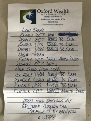
09 Ford Optimum Cooling Fan Profile Settings.JPG

Also I'll post here a copy of my new cooling fan profile that is now loaded in my tune that I set up based on all my prior ECT postings in this thread (that were based on the prior profile that unknowingly had my hi speed fan running constantly even at low ECT regardless of MPH) but retains all of the OEM settings that ensure only continuous low speed fan operation when HVAC is active & speed is below 33 MPH (when HVAC is off & car is moving at all the low speed fan is also shut off due to ECT staying well below the OEM 208*F ECT disable setting...otherwise it cycles on low speed fan at full stop idle for approx 2 1\2 mins then shuts off & comes back on after 25 mins of idling w\ full load on alternator & HVAC off which ups load% from 23% to 25%....takes that long to heat soak this Mishimoto HP rad to drive ECT's back up to the 210*F ECT enable setting so rad is cooling on convection alone w\ Steeda UDP's on OEM water pump.....w\ HVAC on the low speed fan runs continuously w\ load% in the 27%-29% range & ECT at 195*F-197*F steady which indicates thermostat is controlling coolant rate thru rad the same as was happening w\ the hi speed fan running continuously) but is also vetted\proven now to shut fan down completely at speed above the OEM 60 MPH disable setting & stay shut down until speed drops below 33 MPH so no hi speed fan is ever actuated at all now for any reason & the results from this.......shows absolutely NO change in actual operational engine ECT range from prior ECT recordings before profile reset thus exposes the fallacy of resetting these profiles to force excess hi speed fan usage & the potential for hi speed BEC terminal burnout from doing it.....especially when a larger capacity rad\cooling fan equipped w\ the bypass flaps is used. Once I get some hood vents installed this is gonna improve by another factor of magnitude above where it is now...........

Can never burn the hi speed BEC terminals if hi speed fan is never actuated........which is what Ford intended for\how this system to operate w\ their design.......hi speed fan usage only in short temporary emergency instances usually associated by high load% & low MPH operation, not extended operation. Could this system had been designed to operate at 100% DC? Yes it could........but does this really need to be done? My read is in most cases........no.

Kinda follows the misconception centered around thermostat usage......especially if not FI equipped.

The reason why I lowered the low speed ECT enable setting from the OEM setting of 216*F to 210*F is due to my car being driveability tuned on the dyno under the old profile which had the operational ECT well below 208*F (197*F-199*F range) until WOT was applied.

Noticed when idling test was being done under the OEM profile, once the ECT climbed above 212*F the PCM started adding fuel to LTFT's to compensate for the increased ECT off O2 sensor feedback (cat temps were at 998*F so no COT intervention....this is also enabled & set at the OEM setting of 1,650*F to help protect both of my new high dollar MagnaFlow #5461336 CARB-legal cats & both manifold & O2 sensor OT settings are set to 2,000*F to essentially "disable" them operationally but are enabled in tune) until the fan came on & lowered ECT below 212*F then PCM pulled fuel back to the normal LTFT's it usually held.

The 210*F ECT enable setting stopped this from happening.

In future I've figured out how to use my CMCV actuator itself to then reenable the CMCV function in tune but retain all current mappings in both IMRC open\closed tables the same so this appears to be working from the tune perspective w\ all related IMRC DTC's active so when a DAD is plugged up it all looks OEM outside of the Cal\CVN stuff but is actually operating as it is currently w\ CMCV disabled so this will get reinstated at some point in the future......most likely if I get bored & looking for something to do.
 
Last edited:

GlassTop09

Senior Member
Joined
May 24, 2019
Posts
1,145
Reaction score
526
Location
Farmington, NM
FYI..........

Drove car today to Ford dealership to get full service done. Gear resonance is getting lesser & lesser on each 10-13 mi break in drive (hardly hear it anymore on accel, almost gone until around 40 MPH on decel....can hear it but not loud then fades out above 45 MPH & below 35 MPH) then I let it sit rest of the day to cool off. I worked the Tru-Trac's helical gears some more today as well (cut a few hard figure 8's in large empty parking lot to work it......this time I could feel the Eaton Tru-Trac's superior TBR performance over the FoMoCo Trac-Lok start to kick in).

I'm gonna like this LSD..............

Gonna start stretching out the mileage & upping the speeds on a few extended freeway type runs w\ a 30-40 min cooldown in between to start putting a little more load on gear teeth. From what I'm seeing at this point, I may be able to salvage these gears. When I drain the oil after break in is done I'm gonna pull the diff cover & check BL to see where it is after break in (was set at .007" which was on the tight side of the recommended BL specs.....curious to see if it stays within spec range (.009" is the loose side of recommended BL specs). This is where the LubeLocker 8.8" cover gasket is worth it's weight in spades (has been reused 3 times to date w\o any signs of leakage but I bought 2 more of these to have on hand as spares).

We're getting there.........................
 

GlassTop09

Senior Member
Joined
May 24, 2019
Posts
1,145
Reaction score
526
Location
Farmington, NM
FYI................

After installing my Roush 3rd Link I put my jack stands under the rear axle so I could load the axle then run the car in 5th gear to check rear axle while rotating.........found that my RR axle is slightly bent just enough to see it wobble (found after I bought car that it had been wrecked prior my purchase......had ran VIN number before buying it & VIN check showed no accidents so must've been a 1 car accident from hooning & lost control & curbed the RR wheel in addition to the RF of car thus didn't report it to police or insurance.....noted RF fender, RF strut, bumper cover had been replaced & all OEM bumper cover mounting hardware was missing along w\ bumper foam under bumper cover was busted up.....have replaced all mounting hardware & jacked up front bumper foam pieces w\ OEM already. Also noted that the Bullitt wheels on the car when I bought it were not a matched set......now this makes sense as to why) so now explains why I kept hearing the brake caliper noise on the RR when brakes were applied.

So now I gotta round up a replacement RR 31-spline axle to replace this 1 (I'll replace it when I do the rear axle oil change\BL check after gear break in)..........

Heck of a deal.........

:facepalm:
 

GlassTop09

Senior Member
Joined
May 24, 2019
Posts
1,145
Reaction score
526
Location
Farmington, NM
FYI..........

Been checking periodically on the MF #5461336 cats performance from time to time since post #169 as follows:

At 1st checkpoint:
B1 CE ratio @ .152
B2 CE ratio @ .191
CMBT @ 982*F

At 2nd checkpoint:
B1 CE ratio @ .148
B2 CE ratio @ .207
CMBT @ 1011*F

At today's checkpoint:
B1 CE ratio @ .187
B2 CE ratio @ .180
CMBT @ 998*F

To date we got 512 mi thru 36 drive cycles put on these MF #5461336 cats so as you can see, they've settled out very well thus coming in at a consistent CE ratio test result pattern which is falling within the range I thought they should\would based on all the gained data\testing results prior installation & the design data that MF sent me on these cats....

Gonna be interesting cause as of Monday my Stang will be going to On3 Dyno & Performance to upgrade the rear end (Eaton 8.8" Tru-Trac diff, Richmond Elite 8.8" 3.90 gears, Motive Gear 8.8" bearing\shim kit, JEGS 8.8" pinion solid spacer shim kit & Moser 8.8" bearing cap stud kit) so we'll see how much\little net effect on cat CE ratio a .17 T gear ratio change will cause....my gut says a net effect of nil\0 from decreased PCM load% calc's cancelling out any VE % increase from increased running RPM's.....but the acceleration\ all around drivability performance is what I'll be most interested in observing for sure (these 3.90 gears w\ 26" tires should fall approx 1%-2% faster than 4.10\27" but should also be approx 3%-5% slower than 3.73\26" according to my calc's so hopefully balance out & match up well to my engine's TQ output curve across the board to my expectations....good acceleration increase & maintain good all around drivability).
FYI..............
Here are some CE ratio recordings on these MagnaFlow #5461336 cats since the 3.73 gear swap to 3.90 gears & KAM reset\60-40 DFCO MM training\IM Readiness checks completed & at least 12 drive cycles\105 miles completed:

1st checkpoint
B1 CE ratio @ .117
B2 CE ratio @ .168
CMBT @ 998*F

2nd checkpoint
B1 CE ratio @ .126
B2 CE ratio @ .148
CMBT @ 993*F

3rd checkpoint (drive cycle done yesterday, data pulled this morning)
B1 CE ratio @ .129
B2 CE ratio @ .148
CMBT @ 1,235*F (car was never shut down after initial startup.......didn't allow car to idle long before shut down after initial startup & pulled this data this morning during KOEO so the PCM didn't overwrite the recorded running CMBT readings......tested & found PCM is continuously reading CMBT from initial startup to shut down so now I know how to capture the actual running CMBT's going forward.......the 9xx*F CMBT's on all prior recordings are all at full hot engine idle RPM's & do not reflect the actual running CMBT's to achieve the recorded CE ratios).

So far from this data it is appearing that the 3.90 gear\26" dia tire net effective ratio is having a positive net effect on the cat's operational CE ratios. This has to be a function of increased overall engine operating efficiency from PCM load% calc's using the increased mechanical TQ available thru all trans gear\axle gear\tire dia ratios w\ these 3.90 gears even though the operational engine RPM's have increased vs the 3.73 gears thruout all MPH ranges as the rear gear ratio is the only thing that was changed physically & in tune to correct speedo......all else is the same.

Only thing left to see is how the MPG differences will shake out.

So far this is showing more positive overall potential than I expected to see.......a good thing.
 

GlassTop09

Senior Member
Joined
May 24, 2019
Posts
1,145
Reaction score
526
Location
Farmington, NM
FYI................

After installing my Roush 3rd Link I put my jack stands under the rear axle so I could load the axle then run the car in 5th gear to check rear axle while rotating.........found that my RR axle is slightly bent just enough to see it wobble (found after I bought car that it had been wrecked prior my purchase......had ran VIN number before buying it & VIN check showed no accidents so must've been a 1 car accident from hooning & lost control & curbed the RR wheel in addition to the RF of car thus didn't report it to police or insurance.....noted RF fender, RF strut, bumper cover had been replaced & all OEM bumper cover mounting hardware was missing along w\ bumper foam under bumper cover was busted up.....have replaced all mounting hardware & jacked up front bumper foam pieces w\ OEM already. Also noted that the Bullitt wheels on the car when I bought it were not a matched set......now this makes sense as to why) so now explains why I kept hearing the brake caliper noise on the RR when brakes were applied.

So now I gotta round up a replacement RR 31-spline axle to replace this 1 (I'll replace it when I do the rear axle oil change\BL check after gear break in)..........

Heck of a deal.........

:facepalm:
FYI.........
In the meantime I got lucky & scored on a NIB set of Motive Gear F888390 Ford 8.8" 3.90 gears (the 11 pinion\43 ring gear tooth count thus full hunting 3.91 actual ratio) thru Amazon Prime that were sold as "used but like new" due to original packaging damage (internal protective foam busted up around ring gear) but the parts inside were completely untouched thus in pristine condition for a song ($75.95 + tax free shipping) so will be installing these as well as the new replacement axle(s) when I get them.
I was gonna go w\ a set of Nitro Gear equivalents until this deal came along & I couldn't pass it up.

1 look at this Motive Gear 11 pinion\43 ring gear tooth count full hunt version set of 3.90's vs the 9 pinion\35 ring gear tooth count Ford OE 9" pattern non hunt version set of 3.90's (both are 5-cut face milled) tells it all.........they look just like my set of FP 3.73 gears in appearance (11 pinion\41 ring gear tooth count full hunt) w\ the only difference being in the gear tooth cut process used to make them (FP uses face hobbed instead of face milled) so I feel real good about these.

Now as far as axles are concerned, am currently trying to decide between buying a used RR OE 31-spline axle (found several ranging from $165.95 thru $173.95 + tax & shipping from Used Auto Parts Store....a nation-wide junkyard online store where I got my '08 OEM IM thru) or going new aftermarket axle set (Alloy USA 8.8" 31-Spline 05-14 GT, GT500 axle pair......everything except the ABS tone rings) for $279.99 + tax & free shipping thru AM.

I haven't contacted the folks at Used Auto Parts Store yet to see what kind of deal I could cut so am still deciding as to which way to go.
 

GlassTop09

Senior Member
Joined
May 24, 2019
Posts
1,145
Reaction score
526
Location
Farmington, NM
FYI.........
In the meantime I got lucky & scored on a NIB set of Motive Gear F888390 Ford 8.8" 3.90 gears (the 11 pinion\43 ring gear tooth count thus full hunting 3.91 actual ratio) thru Amazon Prime that were sold as "used but like new" due to original packaging damage (internal protective foam busted up around ring gear) but the parts inside were completely untouched thus in pristine condition for a song ($75.95 + tax free shipping) so will be installing these as well as the new replacement axle(s) when I get them.
I was gonna go w\ a set of Nitro Gear equivalents until this deal came along & I couldn't pass it up.

1 look at this Motive Gear 11 pinion\43 ring gear tooth count full hunt version set of 3.90's vs the 9 pinion\35 ring gear tooth count Ford OE 9" pattern non hunt version set of 3.90's (both are 5-cut face milled) tells it all.........they look just like my set of FP 3.73 gears in appearance (11 pinion\41 ring gear tooth count full hunt) w\ the only difference being in the gear tooth cut process used to make them (FP uses face hobbed instead of face milled) so I feel real good about these.

Now as far as axles are concerned, am currently trying to decide between buying a used RR OE 31-spline axle (found several ranging from $165.95 thru $173.95 + tax & shipping from Used Auto Parts Store....a nation-wide junkyard online store where I got my '08 OEM IM thru) or going new aftermarket axle set (Alloy USA 8.8" 31-Spline 05-14 GT, GT500 axle pair......everything except the ABS tone rings) for $279.99 + tax & free shipping thru AM.

I haven't contacted the folks at Used Auto Parts Store yet to see what kind of deal I could cut so am still deciding as to which way to go.
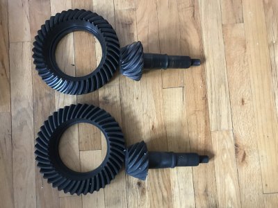
Here is a picture of these Motive Gear F888390 Full Hunting 3.91 ratio (11 pinion\43 ring) gears in comparison to a set of Ford Performance Full Hunting 3.73 ratio (11 pinion\41 ring) gears w\ the major difference being the tooth cut process used to make them:
Ford Performance 3.73 vs Motive Gear 3.91 Both Full Hunting.JPG
The FP 3.73's are the top set (face hobbed), the Motive 3.91's are the bottom set (face milled).
 

GlassTop09

Senior Member
Joined
May 24, 2019
Posts
1,145
Reaction score
526
Location
Farmington, NM
FYI..............
Here are some CE ratio recordings on these MagnaFlow #5461336 cats since the 3.73 gear swap to 3.90 gears & KAM reset\60-40 DFCO MM training\IM Readiness checks completed & at least 12 drive cycles\105 miles completed:

1st checkpoint
B1 CE ratio @ .117
B2 CE ratio @ .168
CMBT @ 998*F

2nd checkpoint
B1 CE ratio @ .126
B2 CE ratio @ .148
CMBT @ 993*F

3rd checkpoint (drive cycle done yesterday, data pulled this morning)
B1 CE ratio @ .129
B2 CE ratio @ .148
CMBT @ 1,235*F (car was never shut down after initial startup.......didn't allow car to idle long before shut down after initial startup & pulled this data this morning during KOEO so the PCM didn't overwrite the recorded running CMBT readings......tested & found PCM is continuously reading CMBT from initial startup to shut down so now I know how to capture the actual running CMBT's going forward.......the 9xx*F CMBT's on all prior recordings are all at full hot engine idle RPM's & do not reflect the actual running CMBT's to achieve the recorded CE ratios).

So far from this data it is appearing that the 3.90 gear\26" dia tire net effective ratio is having a positive net effect on the cat's operational CE ratios. This has to be a function of increased overall engine operating efficiency from PCM load% calc's using the increased mechanical TQ available thru all trans gear\axle gear\tire dia ratios w\ these 3.90 gears even though the operational engine RPM's have increased vs the 3.73 gears thruout all MPH ranges as the rear gear ratio is the only thing that was changed physically & in tune to correct speedo......all else is the same.

Only thing left to see is how the MPG differences will shake out.

So far this is showing more positive overall potential than I expected to see.......a good thing.
FYI............

Followup readings after 16 total drive cycles @ 170 mi:

1st checkpoint:
B1 CE ratio @ .109
B2 CE ratio @ .164
CMBT @ 1,356*F

2nd checkpoint:
B1 CE ratio @ .133
B2 CE ratio @ .176
CMBT @ 1,334*F

3rd checkpoint:
B1 CE ratio @ .148
B2 CE ratio @ .168
CMBT @ 1,290*F

I think this is now settled. Moving up from 3.73 ratio to 3.90 ratio w\ all else being equal did help w\ improving engine operating efficiency\performance in my car's tuned FBO\cammed thus non stock engine as shown\proven by the avg net increase in cat CE performance so making strategic use of rear gear ratio can actually improve (or make worse) emissions output while at the same time also improving (or hurting) performance........to a certain extent depending on how the vehicle is operated.
 

GlassTop09

Senior Member
Joined
May 24, 2019
Posts
1,145
Reaction score
526
Location
Farmington, NM
3rd checkpoint:
B1 CE ratio @ .148
B2 CE ratio @ .168
CMBT @ 1,290*F
FYI..........

The reason why I clipped this particular set of recordings is I changed out my air filter (OEM Ford Performance Bullitt 85mm CAI air filter.....been on car for 18 mos+ & AM\CJ Pony Parts has discontinued providing these as a replacement part so can't get em anymore....were $35 ea) & installed a K&N E-1997 air filter (direct replacement for 08-09 Bullitt 85mm CAI.....only other recourse was WIX--don't make sense to spend the same $75-$85 for a throwaway when the K&N can be cleaned\reused) & reinstalled the same dust sock over the K&N that I had over the FP (to protect it from dust & air borne trash) so all else same except the air filter before I drove car & recorded these numbers over time.

Here are follow up readings afterwards w\ 25 total drive cycles & 257 mi on the clock:
1st checkpoint:
B1 CE ratio @ .148
B2 CE ratio @ .156
CMBT @ 1,246*F

2nd checkpoint:
B1 CE ratio @ .160
B2 CE ratio @ .168
CMBT @ 1,207*F

3rd checkpoint (after putting 47 mi of freeway driving at 70-85 MPH speeds):
B1 CE ratio @ .133
B2 CE ratio @ .129
CMBT @ 1,271*F

The big take away here is the CMBT difference since K&N filter install. Avg CMBT from 1st set of recordings is 1,327*F, the 2nd set of recordings is 1,241*F. This is an 86*F\ 7% drop in avg CMBT......just from changing out an air filter. From an understanding of how cats work, what this avg drop in CMBT is pointing to is an improvement in overall engine combustion efficiency as the increased air flow thru the K&N air filter (shown thru the LTFT avg adjustment fueling gain of +3.1% over both B1 & B2 LTFT readings prior AF changeout that I saw....denotes improved engine VE within the same operational engine RPM ranges) is causing the overall combustion to put out on avg less HC & CO in exhaust (main 2 exhaust gasses that a cat is chemically oxidizing to convert into CO2 & H2O.....are a result of incomplete combustion & chemical oxidation process creates thermal heat) so cats are not oxidizing as much HC & CO in exhaust post AF changeout thus not generating as much CMBT (even though more air\fuel is being used at same AFR) as they were before & also would suggest that NOx output is also decreased as cats use chemical reduction to break apart O2 from N2 which also creates thermal heat--this process also creates free exhaust O2 that the rear O2 sensors should pick up so keep this in mind.

Why the reading of exhaust temp prior cat vs post cat is done to determine if cat is working.......or you can just track the cat CMBT thru a scan tool.........FYI.

These results should also point to potential increased engine power output (engine using more fuel w\ more air but outputting less HC, CO & NOx = more efficient & cleaner thermal energy available to do more work).

I avg'd out the CE ratios across these last 2 sets recorded running 3.90 gears as follows:
1st avg set (FP AF):
B1 @ .130
B2 @ .169
B1\B2 avg @ .1495

2nd avg set (K&N AF):
B1 @ .147
B2 @ .151
B1\B2 avg @ .149

These results show the increase in engine combustion efficiency as engine VE increased from AF changeout but exhaust HC, CO & NOx output levels didn't follow the extra air\fuel usage--a slight overall decrease is observed from this sampling (why I mentioned to keep in mind the free O2 created from NOx reduction thru cat substrates.....avg CE ratio should have gone up from VE increase if all else stayed the same due to more free O2 getting to rear O2 sensors--not less).

Now compare to avg CE ratio numbers of what I recorded running 3.73 gears using same tune, same equip & AF as the 1st avg set after full settling of the MF #5461336 cat substrates in post #174:
B1 @ .162
B2 @ .193
B1\B2 avg @ .1775

Just another way to show the overall efficiency improvement gained from switching gear ratio from 3.73 to 3.90 (even w\ running engine RPM's increased) & engine efficiency improvement using real cat CE ratio numbers that should also show up as increased HP\TQ output from improving VE thru an air filter changeout. If you could see this FP air filter I took out, you wouldn't think it was dirty at all (these dust socks work......started using these on my tuner's recommendation that these prevent dust particles from getting thru but not impede airflow......this proved to be true during my 4-2-20 dyno session as well as the evidence of all the accumulated dust & trash in bottom of my CAI's shroud that the dust sock kept out of my air filter's pleats) but the LTFT results gained thru this K&N filter w\ the very same dust sock installed over it showed how restrictive this OEM FP Bullitt air filter was to air flow thru it.

Car runs excellent & acceleration is very crisp (this cool winter air is helping as well)! All this is confirming the 3.90 gear install was a good choice overall for what I was looking for.

I have a K&N panel filter installed in my Dodge RAM's OEM airbox but no one in my neck of the woods carried K&N replacements for a Bullitt CAI. I ordered this direct from K&N for my Mustang as no one carried these for a Bullitt CAI thru the online stores as well.

Got a set of NGK Iridium IX series plugs (got these on my tuner's recommendation) coming to drop in when I pull these used Champion 9406 Iridium plugs out to inspect them for operation to finish verifying resolution from FRPP IM & Ford F85F-9G444-BD O2 sensor replacement w\ OEM IM w\ CMDP's & used NTK 22060, 22500 O2 sensors (plug tips are still grayish white w\o electrode burn thus no detonation). Engine has performed excellent to date w\ no misfires noticed, heard thru exhaust or recorded in MM since so is a good sign that all has been resolved so we'll see soon.

Provided for informational purposes...................
 

GlassTop09

Senior Member
Joined
May 24, 2019
Posts
1,145
Reaction score
526
Location
Farmington, NM
FYI.........

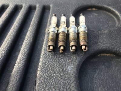
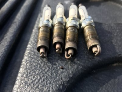
Pulled the used set of Champion 9406 Iridium plugs today (replaced the badly burnt up MC HFJS-24FP plugs I found after FRPP IM changeout & Ford F85F-9G444-BD O2 sensors that were diagnosed to be the main cause of this happening---I posted pictures of them in post #140) & here they are:
Bank 1 Spark Plugs 1-8-22.JPG Bank 2 Spark Plugs 1-8-22.JPG
Top is B1 plugs, bottom is B2 plugs. Looks like a verified confirmed diagnosis & repair as these plugs aren't even hurt in any way. So if you're running a FRPP IM (or any IM or FI setup for that matter) & you got EVAP hooked up to it you might want to check your plugs (especially B1 side if FRPP IM is installed) after you check your EVAP system 1st for operational fidelity then datalog your STFT\LTFT & EVAP_% & EVAP_in\H2O PID's at the same time when PCM is purging EVAP canister to see if the PCM is excessively purging EVAP (look for EVAP_% in excess of 60% & EVAP_in\H2O in excess of -1.5" H2O) then see if you can see the STFT's drop once the PCM closes the CPV & LTFT's fluctuating instead of staying steady at full hot idle.....if you can detect this & B1 is getting the brunt of the damage then the FRPP IM's EVAP port location\routing is the cause of it.......whether the EVAP CPV is found bad or not.
You also should periodically check your NB O2 sensors (WB's as well) thru a cold start (monitor B1S1 & B2S1 output voltage PID's--not B1\B2 STFT PID's--along w\ fuel status 1) as both B1S1\B2S1 O2 sensor voltages should start responding to exhaust (move off 0.0v) BEFORE the PCM switches from OL to CL (status switches off PCM reading inferred exhaust temps thru B1S1\B2S1 O2 sensor heater circuits exceeding 500*F then counts off a 20 sec delay before switching status.....WB's @ 1,242*F) for the O2 sensors to be operating properly. If this doesn't happen then check system for unmetered air entry (vacuum leaks in induction side\air leaks into exhaust around B1S1\B2S1).....if none are found to explain\verify the O2 sensor output voltages staying at 0.0v in CL then O2 sensors are going bad & need to be replaced.......regardless of whether you get a MIL or not.

Installed a set of NGK Iridium IX plugs on my tuner's recommendation gapped @ .044" (the gap they came with.....checked to verify before installing. Book calls for .040"-.050" gap for S197 NA 4.6L V8). Car runs excellent & very smooth so I know going forward that this issue is indeed a dead 1 now on my Stang.

Got it all going my way now & mechanically sound in all systems so these Lunati VooDoo cams can do their thing w\o issue.

:beer: :happythumbs:
 

GlassTop09

Senior Member
Joined
May 24, 2019
Posts
1,145
Reaction score
526
Location
Farmington, NM
FYI...............

I got around to running a test on my Stang to see how much EVAP purging affects fueling correction (will have unmetered fuel vapors & unmetered air entry into IM thru EVAP CPV that the PCM has to account for). The unmetered air from EVAP purge cycles (or any unmetered air for that matter) will also get picked up by the PCM thru its MAF CL error correction based on it comparing predicted MAF vs TPS vs RPM's vs actual MAF at same TPS & RPM's from calibrated MAF tables & looking at the STFT+LTFT AFR correction (been doing a lot of studying.....there's a whole nother topic that I've found that some tuners set intentionally within the SO tune files that can have some adverse effects on CL drivability while trying to prevent learned LTFT application during OL operation from skewing OL base fuel mapping under load that concerns the setting MAF Adaption in the tune.........for another time).

Before starting car, I disconnected CPV from EVAP canister & plugged port on CPV, so air won't be drawn into it while engine is running during full hot idle (left CPV plugged in to prevent PCM flagging a EVAP CPV circuit DTC) then started car & let all come up to full hot idle w\ my trusty Foxwell NT301 scan tool reading live data.

After 45 mins idling at full hot idle, I noted LTFT's settle as follows w\ STFT's switching-B1 @ +7.8%, B2 @ +13.3% for a +5.5% difference between banks w\ CPV disconnected & plugged (I also tested CPV while car was warming up for leakage by removing plug when ECT was <170*F---PCM ignores EVAP so no energizing CPV......CPV tested good w\ no vacuum detected thru open port).

Then I shut down car, pulled plug & reconnected CPV to EVAP canister line & restarted car & allowed car to idle about the same time (engine already at full hot idle) as prior test cycle. This time I also monitored EVAP operation as well. 1st EVAP purge cycle didn't run long (less than 2 mins) due to PCM picking up all air in EVAP canister line from being open while testing w\ CPV disconnected. On the 2nd EVAP purge, the STFT's went heavy -% (down to -13%, -14% area on both banks due to heavily saturated EVAP canister) & it took approx 4 mins for the STFT's to recover back to start some switching then another min after this for PCM to end purge cycle......so far, the LTFT's hadn't corrected yet. On the 3rd purge however, once the STFT's started switching while EVAP purge was still in process, noted the LTFT's make fueling corrections as follows: B1 LTFT dropped from +7.8% to +3.9% (for 3.9% difference) but B2 LTFT dropped only from +13.3% down to +10.2% (for 3.1% difference). Note the amount of correction is very close (only .8% difference) but B1 is 6.3% lower than B2 (compared to prior B1\B2 LTFT readings offset of 5.5% difference this is also the same .8% difference) & on subsequent EVAP purge cycles the LTFT's showed to stay relatively stable maintaining the rough 6.3% offset.......so what is happening here?

What this is showing is how the air distribution pattern within the IM is affected from engine firing order & not from any issue w\ vacuum leaks (system has been smoke tested several times & verified good) & no issues w\ fuel delivery (patterns are too consistent) or NB O2 sensors (have tested several times & verified good) thus explains why on avg, B1 LTFT's usually will be lower than B2 LTFT's thus also explains why B1 cat CE ratio result will usually be lower than B2 cat CE ratio result (more free exhaust O2% in B2 exhaust due to slightly higher air distribution thru B2 cylinders as opposed to B1 cylinders so B2 usually will have a slightly higher VE% split of the total engine VE% output going thru it (using calculated 50.62 lbs\min @ SL @ 6,250 RPM's total VE--100%--for this 4.6L V8 engine displacement to calculate VE % split).

Note: In my On3 tune file, my MAF voltage vs airflow mapping is calibrated\scaled using a WB O2 sensor to hit 50.807 lbs\min (100% VE of 4.6L) across 0-5v range thru my Bullitt CAI's 85mm MAF meter w\ the 85mm calibrated MAF curve matching the stock OEM Ford calibrated 81mm MAF curve @ 36.82 lbs\min (80% VE of 4.6L) across the same 0-5v range when overlayed onto each other--now please explain how a properly scaled MAF curve thru a larger MAF meter is bad for emissions when it mirrors the stock Ford calibrated MAF curve thru a stock Ford 81mm MAF meter thus EPA sanctioned? Also please explain how a larger MAF meter housing than 85mm, using the same Ford calibrated MAF slot sensor, is gonna gain more total engine VE % output above the ideal calculated airmass VE % of engine displacement as set in the tune file for this OEM NA 4.6L V8, which is 50.807 lbs\min.........?

Y'all love to beat on us guys that like to use larger 62mm TB's as overkill, but you praise those who use larger CAI's than OEM as essential, when the only thing that is happening is the tuner is rescaling the calibrated MAF curve from the Ford set max 80% VE scale (limiting engine VE output per TBA across the 0-5v MAF sensor sweep range no matter what you do w\ the rest in the tune) to the ideal engine max 100% VE scale (which will allow you to take full advantage of the rest that the tune settings can provide) so any MAF meter housing larger than 85mm is technically overkill as long as the air filter sq\in area & CAI tube size doesn't impart any additional restrictions to the ideal max air mass flow thru the 85mm MAF meter housing.........

Just saying..................

Now back to the original topic. Using the GlassTop09 calculated 100% VE output numbers above & the 6.3% distribution difference, this says something like 47% of total engine VE output is flowing thru B1 cyls, 53% of total engine VE is flowing thru B2 cyls) thus on avg B1 accounts for 47% of the total HP\TQ output & B2 accounts for 53% of the total HP\TQ output due to air distribution from engine firing order.

Now engine mechanical condition (depending on severity & the cylinders affected) & component design can affect\offset this pattern to a degree but the only way to really effectively change air distribution thru it is to change the engine's firing order.

This LTFT offset pattern between B1\B2 used to drive me crazy trying to figure out why it was happening even though I had concrete test data verifying all else was good........but after the results of this test, not anymore.

Also shows that the EVAP system operation does indeed have a measurable effect on AFR correction, so IMHO these systems need to be checked for integrity\soundness of operation as the unmetered fuel vapors\unmetered air entry thru the EVAP is included in the PCM STFT+LTFT corrections.

Also, in the interest of "science", I have bought an OEM MC replacement CPV to test it against this O'Reilly's aftermarket Standard brand CPV that I bought some 3 1\2 yrs ago (my local Ford dealer doesn't keep these in inventory thus have to order & I couldn't wait on it at the time) to replace the tested leaking original OEM MC CPV to see if the port control design is different between the 2 thus will have an effect on the EVAP purging flow thus corrected LTFT's (but mainly to replace it w\ Ford OEM part just because......).

Posted for informational purposes.........
 
Last edited:

GlassTop09

Senior Member
Joined
May 24, 2019
Posts
1,145
Reaction score
526
Location
Farmington, NM
een doing a lot of studying.....there's a whole nother topic that I've found that some tuners set intentionally within the SO tune files that can have some adverse effects on CL drivability while trying to prevent learned LTFT application during OL operation from skewing OL base fuel mapping under load that concerns the setting MAF Adaption in the tune.........for another time).
Well folks, just letting y'all know that ole GlassTop09 has jumped off the pier & am now swimming on my own.......have bought a HPTuners MPVI2+ interface w\ the 2 credits necessary to now tune my Stang myself (will be getting the Pro Kit upgrade later on to be able to use a WB to do full OL tuning) based off findings concerning the quoted topic above. Also have bought lifetime access to Evans Performance Academy's 2005-2010 Ford Mod Motor HPTuners training (4.0L V6, 4.6L & 5.4L V8's) to use to assist w\ tuning this platform using HPTuners software......from stock to full FI configurations & anywhere in between. This package also comes w\ a tool packet that has all the Excel spreadsheet tools & data written to blend w\ VCM Editor & Scanner for simple copy\paste to assist in all aspects of tuning these engines.

After using my new HPTuners MPVI2+ & VCM Editor\Scanner software in just a short period of time, I'm glad I did make the jump as I've found far more at issue tune wise than I thought I would so now I have fixed\corrected just about all the small stuff I've found that wasn't right\to my liking but not affect the full HP\TQ output as currently gained in about 8 tune revisions to date (making small changes to "sneak up on it" so not to create any drastic issues until I achieve the results I'm looking for & maintain the base tuning at the same time).

Most of what I've found is not actually my tuner's doing (results from using a BAMA tune file) & are small in the grand scheme of things (except 1 item which could have had serious consequences.....a particular necessary safety was found bypassed) but all had a measurable negative effect on CL drivability quality that I wasn't willing to accept (done right you can have both excellent CL drivability & max OL HP\TQ output on demand.....depending on some component choices used such as cams for example) & I didn't want to become a nagging customer so the only recourse was to jump off & tune myself (this part of tuning I'm finding is where it's better to get a remote tune based off actual driving datalogs than on a load bearing dyno from a tuner that is more balanced w\ their tuning thought processes instead of just more performance minded....CL drivability will tend to suffer as a result due to lack of focus on it).

These 3V's really aren't difficult to tune good once you understand how the SO PCM strategy works. Like I've said earlier.......read, study, learn then apply.

In hindsight, I wish I'd have done this sooner...........

PS--I'm still waiting on my MC replacement CPV to get here.........caught up in the current manufacturing\supply chain issues. Pending.........
 
Last edited:

Juice

forum member
Joined
Aug 24, 2017
Posts
4,622
Reaction score
1,905
Funny you should question scaled maf and emissions.
I am currently comparing a few tune variants, and am in the process of re-testing the CAI vs stock airbox with no other changes. On the copperhead pcm, the CAI skews the load calculation by a few percent. While runs good, the CAI has a noticable impact on idle stability and light acceleration or driving up a slight incline, pcm pulls too much timing too quick IMO. On the old fox, I would alter the engine displacement scalar to get load where I wanted it. Not so easy on the copperhead. I have a track day coming up, I am going to compare tunes by laptimes. CAI only this time.
Just sayin'
 

GlassTop09

Senior Member
Joined
May 24, 2019
Posts
1,145
Reaction score
526
Location
Farmington, NM
Funny you should question scaled maf and emissions.
I am currently comparing a few tune variants, and am in the process of re-testing the CAI vs stock airbox with no other changes. On the copperhead pcm, the CAI skews the load calculation by a few percent. While runs good, the CAI has a noticable impact on idle stability and light acceleration or driving up a slight incline, pcm pulls too much timing too quick IMO. On the old fox, I would alter the engine displacement scalar to get load where I wanted it. Not so easy on the copperhead. I have a track day coming up, I am going to compare tunes by laptimes. CAI only this time.
Just sayin'
The MAF Adaption setting is 1 of those settings in the tune that has a measurable positive effect on MAF accuracy as it is constantly making corrections to the MAF errors that the PCM detects during airmass modeling when it uses the predictive airmass calibrated tables (LWFM) as a back check to the incoming MAF airmass calcs off the MAF sensor for errors after smoothing has been applied to the signal voltage, then uses the STFT+LTFT corrections in KAM to then calc a MAF multi in KAM that is 1\2 of the STFT+LTFT fueling corrections to use to correct the found MAF errors to match the predictive LWFM tables so the engine is always getting the correct airmass calc then all else, including fueling, is properly calc'd up front so engine will run at it's best efficiency. This does it's best work during low speed, low RPM engine operations during CL where low airflow velocities thru the MAF can get skewed (the larger the MAF meter section ID is, the worse this gets) so improves overall low speed drivability as well as emissions. Now in order to properly calibrate a MAF table, this setting (along w\ some others) must be disabled to stop it from interfering w\ MAF & LWFM table calibration. But once this is completed, this setting needs to be enabled again. A lot of tuners actually leave this setting disabled after MAF calibration (as I found in my tune file) under the thought that, if I calibrate the MAF & LWFM tables well enough, this isn't needed anymore. This is in reality not true as even the best MAF calibration isn't calibrated to absolute perfection (0% error across the full 0-5v scale) as it's impossible to achieve & can't account for any environmental changes for starters & the only section of airmass that the MAF sensor can actually account for is the air that actually flows thru the MAF sensor's air slot to access the hot wire......the rest is assumed to be the same (the larger the MAF meter housing ID is, the worse this gets). So, this is 1 of those areas where some tuners (even some of the well known tuners that habit the HPTuners forums.....that 1 even tried to tell me that I was overthinking this) are actually creating a low speed, low RPM drivability issue in the tune by leaving this MAF Adaption setting disabled. The engine will run OK w\ this setting disabled (depending on how well the MAF\LWFM tables were calibrated), but not at it's best efficiency & when in OL, this MAF error correction is still going on in the background & PCM is still seeing MAF errors but it doesn't know what to do w\ them cause the switch is disabling it from using the calc'd MAF multis it put in KAM to correct this (remember MAF is still used in OL for load% calcs in SO PCM's), so once the amount of MAF errors reach a point where the PCM has to call a failed MAF, then it overrides everything & makes a fueling correction on it's own off this data (O2 sensors are ignored during OL in SO PCM's) & can force a LTFT correction to fueling in OL overriding the OL base fuel table (under hi engine load when in OL) based off MAF correction alone.......which is not good (usually will lean the fueling out & I've witnessed this very issue happen w\ my car while datalogging it in OL w\ this setting disabled). When this switch is enabled, this now allows the PCM to do it's thing then it will honor the ignore KAM data switch set in OL for LTFT correction data (MAF Adaption needs LTFT correction to work) so all functions as intended in OL, this is still running in the background making all the same corrections in KAM but PCM is just ignoring the KAM while in OL so the strategy coding isn't "broken"......as long as this MAF Adaption switch is reset back to enabled (I've also witnessed this to be true as from the very day I reenabled MAF Adaption in my tune file, the PCM stopped making LTFT corrections during OL & engine low speed low RPM operation started to improve as the PCM now is actually using the strategies as intended). This was also 1 of the reasons I discovered why my STFT+LTFT corrections were skewed high +% (LTFT fueling corrections trying to make up for MAF error modeling......issue w\ this is you lose the fueling, TQ modeling calcs from erroneous MAF calcs up front thus drivability will suffer)....

Just another reason why the Ford engineers did what they did but some just got it in their heads that they know better. It's not so much that they don't know about this, but they are so performance focused w\ tuning in mind that low speed low RPM engine operation doesn't matter to them as making max HP\TQ output does (most are either competitive drag racing or competitive autoX\HPDE\road course racing where mid\high range HP\TQ rules the day) so some speed shops focus here & don't put much if any effort in drivability when, for the most part, all that is mostly needed to maintain good decent drivability is leave the stuff that Ford engineered in the strategies that enhance it enabled.........

There are others that I have since found & have fixed in this SO PCM's tune files that made no sense being done as none of it affected engine max HP\TQ output in the slightest but all of it affected drivability.......especially MPG & you guessed it......emissions.......not for the better either.
 
Last edited:

Juice

forum member
Joined
Aug 24, 2017
Posts
4,622
Reaction score
1,905
I did not read all that, lol.
I have indeed played with maf adaptation setting. I currently just leave it on. I have turned it off try and fine tune maf transfer, but it did not make any noticable difference. Probably because it applies half of the LTFT to the MAF, and I have to go through 5 drive cycles before LTFTs become active.And I have been tweaking my maf based on LTFTs, so I have been able to build custom maf transfer for both, stock and cai. (Stock is lean at idle, and idle only, believe it or not)

BTW, my cai skews load by less than 10% overall. So its not a huge deal at all. But idle does hunt ever so slightly with the CAI. Stock airbox, rock solid.
So it will boil down to feel and laptimes. CAI vs stock airbox. And the winner stays on the car.
 
Last edited:

GlassTop09

Senior Member
Joined
May 24, 2019
Posts
1,145
Reaction score
526
Location
Farmington, NM
This is where I am to date on my tuning process\progress w\ my Stang for all interested.....................(warning, long posting):

1. Reset MAF Adaption back to Enabled--corrects MAF errors by adding 1\2 of LTFT fueling correction back to MAF calcs thru KAM during CL operation only (improves drivability & idle stability). Read in earlier posting for details.

2. Readjust Idle Dashpot Pre-Position & Dashpot Decay settings to clean up ETC hang when transitioning back to idle adaptive control (ETC mimics manual cable control now on decel so no hesitation to transition back to desired idle RPM's). Personal tastes kinda thing.

3. Fixed LWFM IMRC mapping (found IMRC open mapping not copied into the IMRC closed map.....this is done when IMRC switch is set to disabled--CMCV's removed--so PCM will see the same IMRC map data if it accidently references the IMRC closed map data. When IMRC switch is disabled, the PCM usually makes reference to the IMRC open map data automatically by default but can sometimes reference the IMRC closed map data by mistake). Copied the LWFM IMRC open map data into the LWFM IMRC close map......should be obvious as what this could have been causing (LWFM tables are what PCM uses as predictive to check\correct MAF). Checked all the rest of the IMRC maps in tune file for this (spark advance\MBT spark control, VCT control, SD airmass calc's) & fortunately found all the rest properly done so the LWFM IMRC map tables were the only ones that needed fixing. Should help improve drivability & stability by ensuring use of only 1 set of LWFM calibrated table data. My hunch is this could have been a BAMA tune mistake (used them when I initially installed the FRPP IM) that current tuner assumed was done so never checked to make sure from initial tuning on..........

4. Correct fuel stoich AFR from E0 fuel (14.64) to match current E10 fuel (14.08 to 14.13) used to correct EQ Ratio\Lambda. SO PCM's use EQ Ratio formula (actual F\A / F\A stoich) to correct to true Lambda using NB O2 sensors (which are calibrated when made to true Lambda formula--actual air % / stoich air %-02) when the STFT's are switching around 450mv (how SO PCM's use Lambda for all fueling in CL\OL). 14.64 fuel AFR (E0...no ethanol) was more prevalent when these cars were built\sold but now 14.08-14.13 fuel AFR (E10....10% ethanol) is the prevalent pump gas. Did this to correct fuel index ratio that PCM uses in all fueling calcs, TQ modeling calcs up front based off MAF calcs so PCM can account for the embedded O2 in fuel & the BTU value correction from ethanol content in fuel instead of just NB O2 sensors picking up this otherwise unaccounted for O2 in exhaust (my test results show this was approx +3.1% w\ my engine) & calling for extra fuel to account for this (actually is over-enrichening engine due to PCM & NB O2 correction using the wrong fuel stoich AFR in the EQ Ratio\Lambda equation for the actual fuel being used). This can cause excessive fuel usage, issues w\ cats operations causing IM Readiness failures.....especially when you add EVAP purging in the mix & slightly reduce drivability in CL due to PCM not accounting for the embedded O2\BTU in all up front calcs off MAF for E10 fuel. Now the engine will still run Ok (most of these cars......especially the still stock tune cars.....that still have the fuel stoich AFR set @ OEM 14.64 AFR for E0 fuel) since this is mostly occurring during CL operations only (as long as the MAF\LWFM tables are calibrated using a WB O2 sensor in OL & most other map tuning is also done while in OL so when PCM switches into OL, this isn't an issue since WB O2 sensors use true Lambda which don't care about fuel stoich) & will not cause any noticeable ill effects operation wise (mostly at the gas pump on fill ups), but the STFT+LTFT readouts will be skewed higher approx to the amount of unaccounted for O2 embedded in E10 (looking like a vacuum leak that actually doesn't exist). This has absolutely nothing to do w\ a fuel's oct rating......only it's composition\makeup. So be advised.......typed this for knowledge purposes only for S197 SO PCM folks......S197 Copperhead PCM folks need not apply.
To give an example, my datalogged fuel pump DC dropped 1.2% after making this fuel stoich AFR change in tune..........

Sign of the times...............lot of tuners still haven't picked up on this yet, still holding onto the past......

5. Reset CL O2 Temp Enable from 500*F to 700*F, reset delay timing from 15 secs to interpolated 60-30 secs & Heater DC from 28% DC to interpolated 90%-54% DC. Did this to heat up NB O2 sensors more during cold start to ensure that they are good & hot before switching into CL & raised heater DC to ensure that they stay good & hot to maintain accuracy (learned thru EPA training that the OEM settings can cause some NB O2 sensors to cause funky stuff due to not getting hot enough.....especially when LTH's & catted midpipes are installed.....affecting drivability & creating IM Readiness issues. This finding now exposes that I may have removed some perfectly good Ford F85F-9G444-BD NB O2 sensors that I tested\found "bad" prior (slow to come up to temp) that may have only needed these settings raised in tune file to rectify the issues I saw during transition from OL to CL on cold start AND the effects to Catalyst CE Ratio results causing erroneous cat failures (emissions).

Like I said, I wish I'd have bought my HPTuners MPVI2+ interface sooner......

6. Reset OL Fuel TPS Thresh settings & ETC Pedal Pos WOT Start settings to stop PCM from switching into\out of CL-Normal\OL-DD modes too early. The PPWS setting is using the APP to tell PCM when to start transitioning to WOT (OL) from CL-Normal mode then the PCM is looking at the OLFTT settings using engine RPM's & TPS angle% to know when to switch from CL into OL. Most tuners set these settings fairly low so PCM will get into OL-WOT (Power Enrichment) much quicker to enhance engine acceleration & mid\top end performance. This is good for drag racing & autoX\HPDE\road racing (also necessary for 3V FI setups to prevent lean spikes when going into boost under load on very small ETC APP counts from transition from CL to OL), but is a total waste of good fuel on a NA engine that isn't dedicated exclusively for racing usage (PCM is constantly switching from CL Normal to OL-DD\WOT then back on small ETC APP count changes so injectors are constantly pumping good fuel into engine for nothing due to unnecessary PCM cycling between operation modes at low speed low RPM operation, causing some drivability degrading\IM Readiness issues) just because you want the car tuned. Reset my PPWS setting from 250 A\D counts (24% pedal angle) to 340 A\D counts (33% pedal angle) & rescaled OLFTT settings so PCM will still transition into OL-DD\WOT from CL-Normal faster than stock but will stay in CL-Normal mode across most DD driving that uses less than 33% or 1\3 of full APP pedal travel. Should improve drivability, MPG, reduce wear\tear from unnecessary overly rich fuel mixtures by staying in CL longer before commanded to switch.

What happens when tuners are too focused on performance & not balanced enough in thought when tuning these S197's w\ these SO PCM's. Coyotes using Copperhead & later PCM's don't have this issue since they use CL exclusively once off cold start.

7. Corrected ETC Throttle Body modeling to better rep my FR 62mm TB's Predicted Throttle Angle & Effective Area data (TB body ID & butterfly OD area). Copied the TB data for an OEM Ford Racing 60mm TB (used w\ the 2010 GT500's) into my tune file to use w\ my Ford Racing 62mm TB (was still using the stock TB data for an OEM Ford 55mm TB) to get a much closer match of TB angle effective area to air load calcs off MAF lbs\min so PCM will properly calc TQ loads to clean up IPC TQ errors created from the mismatch & better maintain good stable engine RPM control for improved drivability & performance. This took away the rest of my engine's small idle hunting issues.....now idle is dead solid for a DBW system. Noticed that thruout all Ford TB tuning in tune files from 2005 thru 2010 Ford Mod Motors, regardless of TB size, outside of the actual TB modeling, Ford used the exact same ETC TB control settings so as long as the TB modeling data is Ford tuned AND the data used isn't oversized for the TB it is being used for, swapping the data is simply a plug & play thing....no other adjustments needed......just works.

Why this wasn't done up front.....can't answer but is just too easy to rectify.

8. Corrected in TQ modeling the IPC TQ Error Max setting (set this back to stock setting of 25,000). This is a safety to keep engine from runaway if IPC TQ errors exceed the setting amount by PCM fully closing the TB & going into Limp Mode off excessively high TQ errors. Tuners usually set this setting high enough to get it out of the way (usually around 100,000) when tuning TQ tables, spark tables, VCT tables & ETC control to allow clean up any excessive IPC TQ errors w\o inducing Limp Mode, once done then should be set back to 25,000.....but either some tuners forget to do this after tuning is complete or some intentionally leave this set high so it won't interfere w\ high load engine operations (such as drag racing for example). I found mine set at 500,000......kinda implies intent to me (my hunch this is BAMA tuning leftover & not current tuner, but he left it as found.......) thus this safety was defeated in my tune.....IMHO this is not good, especially if car is mostly driven on the street (very dangerous......may have a lot to do w\ a lot of Mustang control loss crashing memes due to sub par tuning). Reset this back to stock after datalogging tune to ensure engine IPC TQ errors were very low (found mine were <1,000 at the most so all actual tuning is done very well overall) to enable this safety to prevent this if something goes awry causing a TB runaway.

I think I'm in a good place now w\ all that is going on under the hood after today.

FYI.
 
Last edited:

Juice

forum member
Joined
Aug 24, 2017
Posts
4,622
Reaction score
1,905
I'm going to experiment with the speed density calculator. I have not yet to date, as the engine is stock except for exhaust and occasional CAI.

I felt the same way after getting the SCT software. Why did I wait so long?
 

Support us!

Support Us - Become A Supporting Member Today!

Click Here For Details

Sponsor Links

Banner image
Back
Top